Prototyping · Study deck
Hardware Build Discipline and Debugging
Picture a prototype that worked yesterday but fails after three wires and a code update changed together.
Voltage Vera is your guide for this deck.
After studying this chapter
Learning objectives
You will be able to:
- Explain: On a new board, inspect rail-to-ground resistance before first power, then apply power with a limit low enough to reveal a short without burning a trace or regulator.
- Explain: The next panel keeps firmware and supply settings the same, repeats pump startup, and asks for scope captures of both rails and the reset pin, plus the brownout log.
- Explain: For IoT prototypes, the risky moments are often transitions: boot, radio transmit, sensor warmup, actuator start, sleep entry, wake source, OTA reboot, enclosure close, and cable strain.
- Explain: Hardware best practice is not extra paperwork.
Major section
Debugging Discipline Starts Early
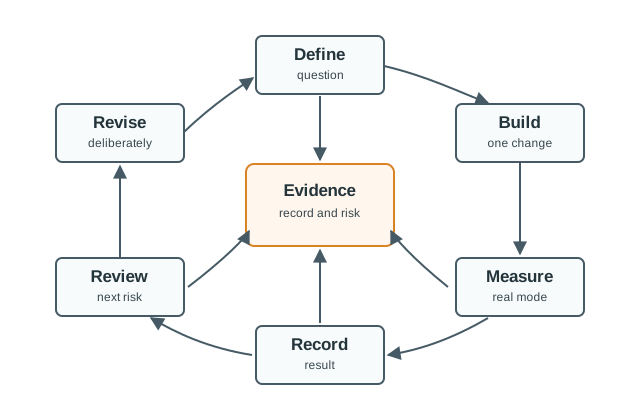
Hardware best practice is not extra paperwork.
- A startup surge through the shared path is shown dropping the regulator input below its required level, which can explain an ESP32 reset.
- A separate supply path is only a candidate fix.
- The record holds wiring revision, firmware commit, and capture together.
Major section
Debugging Discipline Starts Early (continued)
The next panel keeps firmware and supply settings the same, repeats pump startup, and asks for scope captures of both rails and the reset pin, plus the brownout log.
- For IoT prototypes, the risky moments are often transitions: boot, radio transmit, sensor warmup, actuator start, sleep entry, wake source, OTA reboot, enclosure close, and cable strain.
- A bench pass at idle does not prove those transitions are safe.
- That build should prove the rail voltage, the I2C address, one believable reading, and the firmware identity.
- The next one might add Wi-Fi or LoRaWAN transmit and measure current during association or uplink.
Major section
Bring Up Power Before Features
A current-limited bench supply, digital multimeter, oscilloscope, logic analyzer, and serial console can answer most first-order questions before application firmware is blamed.
- A practical bring-up log should start before code changes.
- On a new board, inspect rail-to-ground resistance before first power, then apply power with a limit low enough to reveal a short without burning a trace or regulator.
- For buses and timing, use the tool that can see the failure.
Major section
Bring Up Power Before Features (continued)
If the 3.3 V rail is correct, record the idle current and reset state before attaching sensors, radios, storage, displays, or loads.
- If the rail is wrong, stop and isolate the power section instead of loading the full application.
- A multimeter can prove a missing rail, but it cannot show I2C clock stretching, SPI mode errors, UART baud mismatch, PWM edge timing, or reset pulses.
- A Saleae Logic or similar logic analyzer can show an I2C address NACK, a stuck bus, or a chip-select conflict.
Major section
Test Points Are Design Features
Good hardware notes let someone else repeat the setup, see the same symptom, and understand why the next revision is justified.
- A rail test pad near the load can show whether the voltage drop happens at the regulator, the connector, or the actuator.
- A current-measurement jumper can separate microcontroller sleep current from sensor leakage or a radio module that never entered low-power mode.
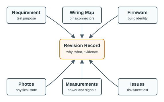
- Under the hood, hardware evidence also needs identity control.
Major section
Documentation That Helps Debugging
Without that link, a rail capture or issue note could belong to an earlier assembly.
- The revision record then shows what changed and why, while the risks and next test keep unresolved behavior visible.
- A reviewer can check whether the result applies to this exact build and repeat the test after a connector, power path, or firmware change.
Major section
Power And Signal Checks
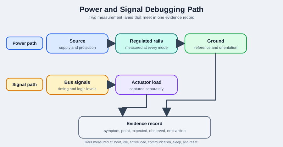
The source starts at 5.00 V, but the example assigns a 1.50 A surge to a 2.00 Ω shared path.
- That gives a 3.00 V drop and only 2.00 V at the regulator input, below the shown 3.60 V requirement.
- the Power and signal debugging path diagram separates the worked pump voltage drop from the traces still needed on the bench.
Major section
Bring-Up Checklist
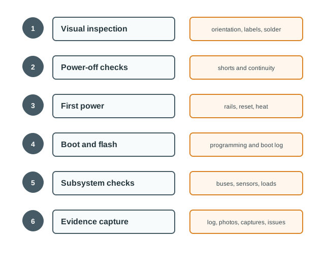
Board bring-up should proceed from low-risk checks to active firmware behavior.
- Wrong rails stop the process at the power section instead of loading the application.
- The final evidence stage saves measurements, logs, photographs, captures, pass or fail decisions, and known issues.
- That ordering confines faults and makes the next retest start from the last proven boundary.
Major section
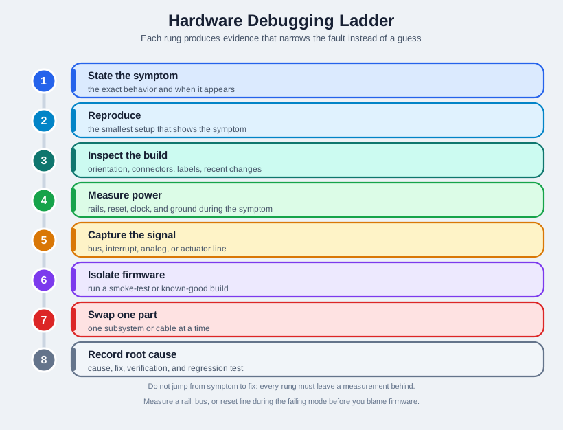
Debugging Ladder
Each step should produce evidence that narrows the fault.
- A bus or actuator capture can show a failure that a static voltage reading misses.
- A known-good firmware build helps separate hardware from code; change only one part or subsystem before repeating the same check.
- the Hardware debugging ladder diagram orders the observations that can narrow a hardware fault.
- Each rung has a distinct job, so skipping capture can turn a plausible fix into an untested guess.
Major section
Incremental Examples
A learner connects a BME280 temperature, pressure, and humidity sensor to an ESP32 development board.
- If the sensor does not answer, the first checks are power, ground, address, bus pull-ups, connector orientation, and logic level before changing application code.
- A prototype uses a 5 V relay module to switch a small pump while an ESP32 reads a flow sensor.
- The symptom is a reset whenever the pump starts.
Major section
Common Failure Patterns
No revision record: The next build repeats a previous failure because the team did not record the cause and verification.
- No test access: Signals disappear inside an enclosure, connector, or layout before the team can probe them.
- Unlabeled wiring: The prototype works only while the original builder remembers the jumper map.
- Firmware blamed first: Code is rewritten while the real issue is reset, grounding, bus pullup, connector orientation, or load behavior.
Deck summary
Key takeaways
Hardware best practice is not extra paperwork.
- The next panel keeps firmware and supply settings the same, repeats pump startup, and asks for scope captures of both rails and the reset pin, plus the brownout log.
- A current-limited bench supply, digital multimeter, oscilloscope, logic analyzer, and serial console can answer most first-order questions before application firmware is blamed.
- If the 3.3 V rail is correct, record the idle current and reset state before attaching sensors, radios, storage, displays, or loads.
- Good hardware notes let someone else repeat the setup, see the same symptom, and understand why the next revision is justified.
Retrieval practice
Recall check 1 of 5
Voltage Vera says: answer from memory, then check your reasoning.
Q1Per this chapter's worked numbers, an unclamped 5 V relay coil (I approximately 70.4 mA, L approximately 0.3 H) is switched off in about 1 microsecond. Roughly how large is the resulting flyback voltage spike, and what does the chapter say this number means for the design?
Show answer
Answer: B see answers page
Retrieval practice
Recall check 2 of 5
Voltage Vera says: answer from memory, then check your reasoning.
Q2A sensor board will be sealed in an enclosure. Which design change best preserves test access?
Show answer
Answer: C Named access lets a reviewer inspect the live circuit.
Retrieval practice
Recall check 3 of 5
Voltage Vera says: answer from memory, then check your reasoning.
Q3Per this chapter's I2C sensor bring-up example, if a BME280 does not respond on the I2C bus, what should be checked first, before changing application code?
Show answer
Answer: C see answers page
Retrieval practice
Recall check 4 of 5
Voltage Vera says: answer from memory, then check your reasoning.
Q4Per this chapter's advanced battery-gateway example, why might a field gateway pass a bench demo and still fail once deployed?
Show answer
Answer: C see answers page
Retrieval practice
Recall check 5 of 5
Voltage Vera says: answer from memory, then check your reasoning.
Q5A prototype resets whenever a motor starts. What is the best first debugging sequence?
Show answer
Answer: A The symptom may come from voltage drop, reset behavior, wiring, load current, or firmware timing.
Print reference
Answers 1 of 3
Answer key.
- B · The chapter's worked example computes V_L = L x dI/dt with catalog-typical L approximately 0.3 H, I approximately 70.4 mA, switched off in about 1 microsecond: V_L = 0.3 x (0.0704/0.000001) is about 21,127 V. The chapter calls this 'a number that is not meant to be survived, which is exactly why a flyback diode belongs in the design rather than being optional.'.
- C · Named access lets a reviewer inspect the live circuit.
Print reference
Answers 2 of 3
Answer key.
- C · If the sensor does not answer, the first checks are power, ground, address, bus pull-ups, connector orientation, and logic level before changing application code.
Print reference
Answers 3 of 3
Answer key.
- C · The chapter asks 'whether the prototype survives the transitions that a bench demo often hides: boot, radio burst, deep sleep, wake interrupt, charge state, enclosure close, antenna placement, and firmware recovery,' and recommends measuring sleep current, transmit current, startup inrush, brownout threshold, charger behavior, and wake latency with instrumentation such as a Power Profiler Kit II, Otii Arc, or Joulescope rather than trusting a bench-idle reading.
- A · The symptom may come from voltage drop, reset behavior, wiring, load current, or firmware timing.