Prototyping · Study deck

Microcontroller Programming: Timing and Reliability

Digital pins now behave as expected, but sensor readings and timed work add new failure paths.

Voltage Vera is your guide for this deck.

microcontrollerprogrammingessentials
iotclass.org

After studying this chapter

Learning objectives

You will be able to:

  • Explain: Feeding it right before a long delay() or an unbounded wait defeats the purpose, because the feed call proves nothing about whether the rest of the loop would actually have completed.
  • Explain: On Cortex-M4, xPSR is the combined view of three overlapping status-register roles: the Application Program Status Register (APSR), Interrupt Program Status Register (IPSR), and Execution Program Status Register (EPSR).
  • Explain: The non-blocking half instead shows the millis() test interleaving A, B, and C, so elapsed time becomes a condition to check rather than a command that halts execution.
  • interpret ADC evidence
iotclass.org

Major section

Non-Blocking Timing With millis()
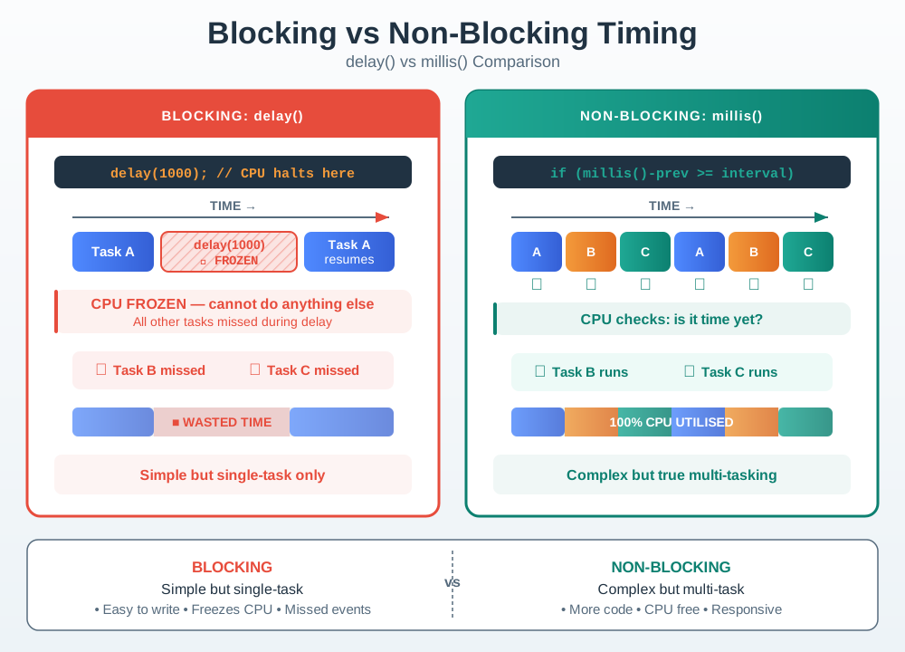
While the loop is delayed, firmware cannot read a button, service a state machine, check a timeout, or publish a new sensor sample.

  • The replacement pattern is to compare elapsed time.
  • Responsiveness is easier to judge when the two timing models share one time axis.
  • The non-blocking half instead shows the millis() test interleaving A, B, and C, so elapsed time becomes a condition to check rather than a command that halts execution.
  • That contrast connects directly to the running firmware narrative: a prototype that must sample, communicate, and react should demonstrate that every duty still gets a turn within its deadline.
Blocking vs Non-Blocking Timing
iotclass.org

Major section

Interrupt Top and Bottom Halves

Interrupts are for urgent hardware events.

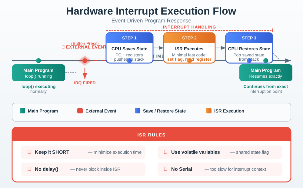
  • An interrupt service routine pauses normal execution, runs a small handler, then returns to the main context.
  • The safest beginner pattern is to set a flag in the ISR and do the real work in loop().
  • IRAM_ATTR is ESP32-specific.
An interrupt briefly saves context, performs a tiny urgent action, restores context, and leaves slow work to normal code.
iotclass.org

Major section

Watchdog Timer: A Reliability Backstop

Feeding it right before a long delay() or an unbounded wait defeats the purpose, because the feed call proves nothing about whether the rest of the loop would actually have completed.

  • Interrupts and millis() scheduling keep the loop responsive to events its author anticipated.
  • wdt_enable() and wdt_reset() are the classic AVR watchdog API from the AVR watchdog header.
  • A watchdog only protects a loop that is already structured to return often.
iotclass.org

Major section

Compiler And Fixed-Point Lab

More fractional bits improve resolution but reduce range.

  • A compiler can schedule independent instructions, use vector instructions when the target has them, and replace a short branch with predicated work.
  • None of those transformations removes the need for evidence.
  • Fixed-point arithmetic makes that evidence boundary visible.

Try it: Compiler And Fixed-Point Lab in the chapter

iotclass.org

Major section

Cortex-M core and address maps

Actual cacheability, MPU attributes, bus fabric, and external-memory support are core- and SoC-specific.

  • In everyday MCU firmware the critical ranges are normally code, on-chip SRAM, peripherals, and the System Control Space.
  • Memory-mapped I/O means a peripheral owns addresses just as RAM owns addresses, but reads and writes are not ordinary storage operations.
  • The frame pointer is a convention, not a new architectural register.
iotclass.org

Major section

Cortex-M status registers

On Cortex-M4, xPSR is the combined view of three overlapping status-register roles: the Application Program Status Register (APSR), Interrupt Program Status Register (IPSR), and Execution Program Status Register (EPSR).

  • The arithmetic flags are easiest to separate with two examples.
  • 0xFFFFFFFF + 1 produces zero, so Z=1 and C=1; interpreted as signed −1+1-1+1−1+1, it does not overflow, so V=0.
  • IPSR gives exception context, not a generic interrupt-enabled flag.
iotclass.org

Major section

Cortex-M status registers (continued)

Handler mode has a nonzero exception number; Thread mode reads zero.

  • EPSR's ICI/IT fields are execution-resume state maintained by the processor around interrupted multi-cycle instructions or IT blocks.
  • Application code should not treat them as spare flags.
  • When a debugger shows xPSR, decode each view by its own meaning: arithmetic result in APSR, active exception in IPSR, and execution state in EPSR.
Cortex-M xPSR anatomy combining APSR condition flags, IPSR exception number, and EPSR Thumb and ICI or IT execution state.
iotclass.org

Major section

Memory Hierarchy For IoT Firmware

A design review should keep volatile working memory, immutable boot code, updateable firmware, calibration values, event logs, and high-write counters separate before selecting a device.

  • Endurance is a workload calculation: a one-million-cycle cell can still fail early if firmware rewrites it many times per second without wear distribution.
  • Below it, Arguments and return assigns r0-r3, while Control the call identifies r13 SP, r14 LR, and r15 PC as the registers that reconstruct execution flow.
  • Their xPSR combination is a convenient snapshot, not a single undifferentiated meaning.
Cortex-M address regions paired with core-register groups, calling-convention roles, frame pointer, stack pointer, link register, and program counter.
iotclass.org

Deck summary

Key takeaways

While the loop is delayed, firmware cannot read a button, service a state machine, check a timeout, or publish a new sensor sample.

  • Interrupts are for urgent hardware events.
  • Feeding it right before a long delay() or an unbounded wait defeats the purpose, because the feed call proves nothing about whether the rest of the loop would actually have completed.
  • More fractional bits improve resolution but reduce range.
  • Actual cacheability, MPU attributes, bus fabric, and external-memory support are core- and SoC-specific.
iotclass.org

Retrieval practice

Recall check 1 of 3

Voltage Vera says: answer from memory, then check your reasoning.

Q1This chapter states the LM35 sensor outputs 10 mV per degree C, and its lm35CelsiusFromVoltage() function returns voltage * 100.0. If the ADC-derived voltage is 0.250 V, what temperature does the function return, and why multiply by 100.0 rather than some other factor?

A2.5 degrees C, because the code divides the 0.250 V reading by 100.0 rather than multiplying it at all.
B25.0 degrees C only at a 3.3 V VREF, since changing VREF changes the LM35's 100.0 slope.
C25.0 degrees C: 10 mV per degree C means 100 degrees C per volt, so 0.250 V times 100.0 gives 25.0.
D0.0025 degrees C because the voltage must first be scaled to millivolts for this function.
Show answer

Answer: C see answers page

iotclass.org

Retrieval practice

Recall check 2 of 3

Voltage Vera says: answer from memory, then check your reasoning.

Q2This chapter's non-blocking timing pattern compares elapsed time using now - lastBlinkMs >= 500 rather than checking whether lastBlinkMs + 500 has passed. Per the chapter, why is the subtraction form the standard pattern?

AIt eliminates separate last-run variables because a shared loop timer can schedule both LED and sensor work.
BSubtracting elapsed millis() remains correct across a rollover; adding the interval can fail there.
CIt lets firmware read millis() just once at startup and infer all later elapsed intervals.
DIt puts LED and sensor work on a 500 ms schedule because one interval governs both tasks.
Show answer

Answer: B The chapter states the subtraction form now - lastTime >= interval 'continues to work when millis() rolls over,' which is why it replaces a naive lastTime + interval <= now comparison.

iotclass.org

Retrieval practice

Recall check 3 of 3

Voltage Vera says: answer from memory, then check your reasoning.

Q3A button input is configured as INPUT with no pull-up or pull-down resistor. What is the main risk when the button is not pressed?

AReinitialize the input pin on each loop pass to stabilize its open circuit.
BThe input can float and produce unreliable HIGH or LOW readings.
CUse the startup reading in setup() as the button's default state.
DPut sensor checks inside a blocking delay() in loop().
Show answer

Answer: B GPIO input behavior is part firmware and part circuit design.

iotclass.org

Print reference

Answers 1 of 2

Answer key.

  1. C · The chapter states the LM35 outputs 10 mV per degree C, so each volt of sensor output represents 100 degrees C (1 V / 0.010 V-per-degree = 100). The lm35CelsiusFromVoltage() function encodes exactly that: voltage * 100.0. At 0.250 V, the result is 25.0 degrees C, independent of the board's ADC reference voltage, which only affects the earlier raw-to-voltage step.
iotclass.org

Print reference

Answers 2 of 2

Answer key.

  1. B · The chapter states the subtraction form now - lastTime >= interval 'continues to work when millis() rolls over,' which is why it replaces a naive lastTime + interval <= now comparison.
  2. B · GPIO input behavior is part firmware and part circuit design.
iotclass.org