Prototyping · Study deck
Microcontroller Programming: Setup and GPIO
This first route takes a board from toolchain setup, the set of tools that builds and loads its program, through a testable GPIO sketch.
Voltage Vera is your guide for this deck.
After studying this chapter
Learning objectives
You will be able to:
- Explain the setup() and loop() execution model used by Arduino-style firmware.
- Configure GPIO pins for digital output, digital input, and pull-up button input.
- Read analog sensor values and convert raw ADC counts into engineering units with board-specific limits.
- Use serial output as an evidence stream for debugging and prototype review.
Major section
Overview · In 60 Seconds
This first route takes a board from toolchain setup, the set of tools that builds and loads its program, through a testable GPIO sketch.
- GPIO means general-purpose input/output pins.
- A sketch is the small program used here to read or set those pins.
- Stable inputs give repeatable readings when the same signal is applied.
Major section
Phoebe's Field Notes: delay(250) Is A Nyquist Choice, Whether The Sketch Knows It Or Not · Start With the Story
The mathematical gist. Delay(250) checks the button every 250 ms, so it can miss a 100 ms press.
- Poll more often than every 100 ms; a 50 ms interval (20 checks per second) gives margin.
- For a band-limited sensor signal sampled every 250 ms, the sample rate is 4 Hz and the Nyquist frequency is 2 Hz.
- Separately, a 12-bit ADC over 3.3 V has 0.806 mV steps, which an LM35's 10 mV/°C slope turns into 0.0806 °C per code.
Major section
Firmware Makes Wiring Behave
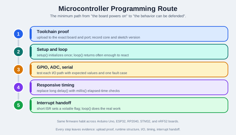
The code must configure pins, sample inputs, update outputs, keep time, and report enough evidence to show what the prototype actually did.
- The safest beginner habit is to keep each loop pass short.
- Good firmware turns wiring into behavior that another engineer can reproduce from board profile, code version, wiring, serial output, and timing notes.
Major section
Prove Firmware Steps Separately
If that record is missing, later sensor or network debugging starts on uncertain ground.
- A digital output test should prove the pin can drive the selected LED, relay input, MOSFET gate, or indicator within the board's current and voltage limits.
- A digital input test should prove the default state, pull-up or pull-down choice, debounce behavior, and disconnected-wire failure mode.
- For timing, replace long delay() calls as soon as two jobs must share the device.
Major section
Under the Hood: The Loop Is a Scheduler
The hidden machinery differs by board.
- Blocking code can still starve sensor reads, watchdog resets, communication retries, or actuator safety checks.
- Each task decides whether it is time to run, does bounded work, records evidence, and gives control back.
- On a classic AVR Arduino, the sketch often runs close to the foreground loop model.
Major section
Under the Hood: The Loop Is a Scheduler (continued)
That pattern scales better when the prototype later adds networking, storage, OTA updates, or power management.
- On ESP32 Arduino, loop() runs inside a FreeRTOS task while Wi-Fi, Bluetooth, timers, and system services use other tasks and interrupts.
- On RP2040, dual-core behavior and PIO peripherals can move timing-sensitive work outside the normal loop.
- On a Cortex-M style board, that hidden machinery has a concrete execution model.
Major section
Under the Hood: The Loop Is a Scheduler (continued)
Most MCU peripherals are controlled through registers exposed in the processor memory map.
- On nRF52 or STM32 boards, vendor SDK layers, timer peripherals, DMA, and low-power modes can change which code runs while the main loop appears idle.
- Normal application work runs in thread mode; an interrupt briefly runs in handler mode, then returns.
- Small transfers, such as one UART byte or one ADC sample, can be handled directly.
Major section
Under the Hood: The Loop Is a Scheduler (continued)
Core registers such as r0 through r3 carry arguments and return values, while r13, r14, and r15 act as the stack pointer, link register, and program counter.
- Two ordinary lines of C -- a = a + 1; in loop(), a = a: 1; in a handler -- are not one CPU instruction each.
- Most Arduino-style firmware defaults to the third strategy because it keeps latency predictable without demanding careful critical-section bookkeeping inside every handler.
- That avoids waking the CPU for every byte or sample, but it creates a buffer-ownership contract that must be measured and documented.
Major section
Under the Hood: The Loop Is a Scheduler (continued)
Those differences do not remove the beginner model; they make its evidence more important.
- A safe interrupt path records only the event that must not be missed and leaves serial printing, network sends, memory allocation, and long calculations outside the ISR.
- A safe timer path proves that elapsed-time comparisons survive counter wraparound and do not assume a fixed loop speed.
- When the loop is treated as a scheduler, the prototype can grow without every new feature becoming another blocking delay.
- These constraints also explain why examples that work alone can fail when combined without timing budgets.
Major section
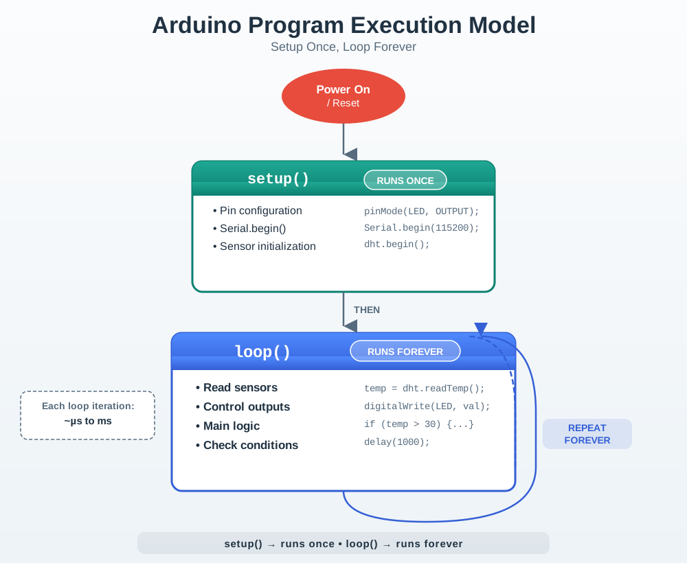
setup() And loop()
Behind that simple structure, the board support package initializes clocks, memory, pins, timers, and runtime services.
- Some boards run loop() directly; ESP32 Arduino runs it as a FreeRTOS task.
- Execution then enters loop and repeatedly reads inputs, updates outputs, processes state, and reports evidence.
- Responsive firmware keeps each loop visit short enough for the other recurring duties to run.
Major section
Checkpoint: Common Setup Mistakes · First Sketch: Blink With Evidence
This version still uses delay() because it is a first hardware proof.
- Assuming every board has LED_BUILTIN on the same pin.
- Using Wi-Fi, ADC, or interrupt examples from a different board family without checking pin support.
- Later in the chapter, you will replace that blocking pattern with millis().
Major section
Sketch Syntax Review
Arduino sketches use ordinary C/C++ building blocks, but the review question is always tied to firmware behavior.
- Arrays and strings need the same discipline.
- Arrays are useful for fixed sensor windows, lookup tables, calibration points, or pin lists, but the index must stay inside the declared length.
- Character arrays and Arduino String objects can hold labels or serial messages, yet repeated dynamic string growth can fragment memory on small boards.
Major section
GPIO: Output, Input, And Pull-Ups · Floating Inputs Are Not Random Bugs
GPIO pins are general-purpose digital pins.
- The same physical pin may not support every function, so always check the board pinout.
- INPUT_PULLUP makes an open button read HIGH and a pressed button read LOW, so the logic must use that polarity.
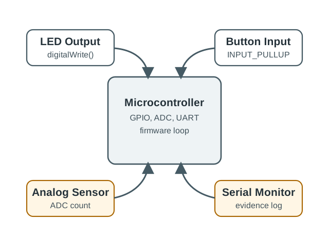
- the GPIO, ADC, and serial signal paths diagram keeps digital pin behavior, analog conversion, and serial evidence distinct.
- UART sends an observable result to the computer and evidence log.
Deck summary
Key takeaways
This first route takes a board from toolchain setup, the set of tools that builds and loads its program, through a testable GPIO sketch.
- The mathematical gist. Delay(250) checks the button every 250 ms, so it can miss a 100 ms press.
- The code must configure pins, sample inputs, update outputs, keep time, and report enough evidence to show what the prototype actually did.
- If that record is missing, later sensor or network debugging starts on uncertain ground.
- The hidden machinery differs by board.
Retrieval practice
Recall check 1 of 6
Voltage Vera says: answer from memory, then check your reasoning.
Q1A firmware demo works only on its creator’s desk. Which evidence packet makes it repeatable?
Show answer
Answer: B The packet preserves the inputs and observations another engineer must replay.
Retrieval practice
Recall check 2 of 6
Voltage Vera says: answer from memory, then check your reasoning.
Q2A raw analog count is called a temperature. What must firmware record before that claim is valid?
Show answer
Answer: D The conversion depends on board-specific electrical limits and sensor units.
Retrieval practice
Recall check 3 of 6
Voltage Vera says: answer from memory, then check your reasoning.
Q3A prototype prints raw ADC counts from a temperature sensor. What turns those counts into a defensible temperature?
Show answer
Answer: C Raw counts need both converter and sensor contracts.
Retrieval practice
Recall check 4 of 6
Voltage Vera says: answer from memory, then check your reasoning.
Q4Per this chapter's under-the-hood section on MCU peripherals, what does using DMA for a larger or faster transfer change compared to handling one UART byte or one ADC sample directly?
Show answer
Answer: B The chapter contrasts direct handling ('small transfers.
Retrieval practice
Recall check 5 of 6
Voltage Vera says: answer from memory, then check your reasoning.
Q5A firmware loop misses safety checks while waiting between samples. Which change fits the chapter?
Show answer
Answer: C Bounded work and elapsed-time scheduling keep the loop responsive.
Retrieval practice
Recall check 6 of 6
Voltage Vera says: answer from memory, then check your reasoning.
Q6A button uses an internal pull-up input. What reading should firmware expect when the button closes to ground?
Show answer
Answer: B Closing the button connects the input to ground.
Print reference
Answers
Answer key.
- B · The packet preserves the inputs and observations another engineer must replay.
- D · The conversion depends on board-specific electrical limits and sensor units.
- C · Raw counts need both converter and sensor contracts.
- B · The chapter contrasts direct handling ('small transfers.
- C · Bounded work and elapsed-time scheduling keep the loop responsive.
- B · Closing the button connects the input to ground.