Electronics & Circuits · Study deck
DAC and PWM: Actuator Selection and Validation
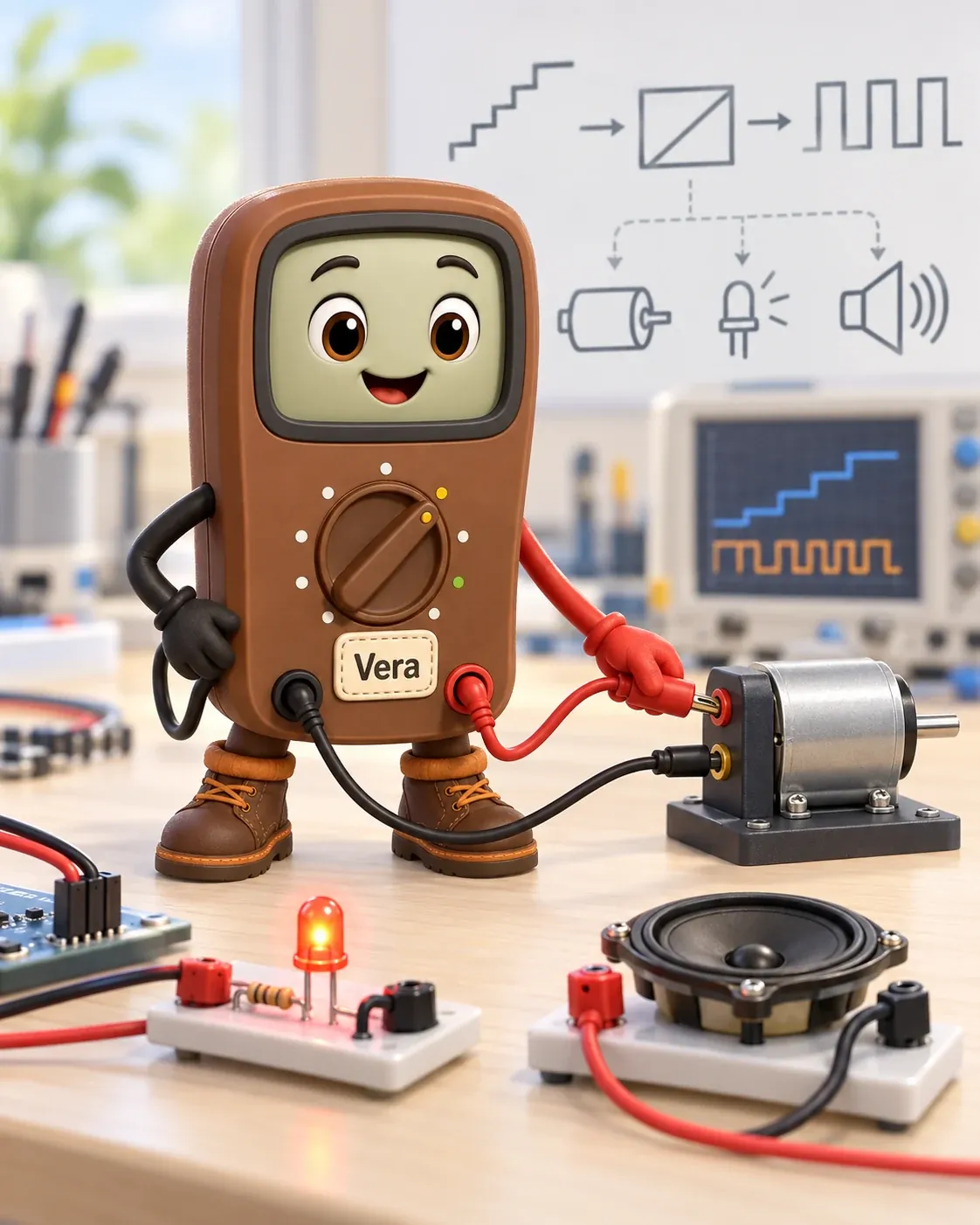
An LED or motor is an actuator, a device that acts on its surroundings; an audio input is a different kind of load.
Voltage Vera is your guide for this deck.

After studying this chapter
Learning objectives
You will be able to:
- Explain: That observation connects duty-cycle arithmetic to the selection rule: PWM suits tolerant loads, while quiet bias and measurement signals need filtering or a true DAC.
- Explain: An LED or motor is an actuator, a device that acts on its surroundings; an audio input is a different kind of load.
- Explain: This page turns those ideas into a design contract: what the load actually sees, what timer settings cost, and what error matters most.
- Explain: Whatever smooths it — the load's own sluggishness or a deliberate RC low-pass filter — is really just attenuating those harmonics.
Major section
Start With the Decision
An LED or motor is an actuator, a device that acts on its surroundings; an audio input is a different kind of load.
- PWM sends on-off pulses; a filter can smooth them.
- Human perception:: LED dimming (eye can't see >100 Hz flicker).
- The eye cannot detect the flicker, and PWM saves scarce DAC outputs.
Major section
Applied: PWM vs DAC Output
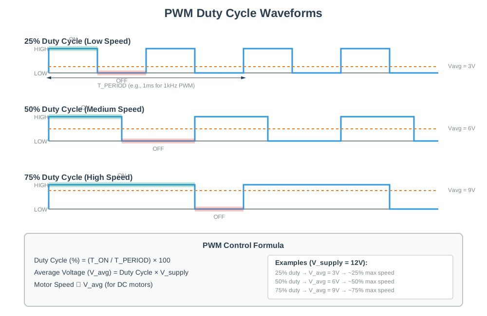
The choice between PWM and DAC is a contract about duty-cycle resolution, frequency, filtering, settling time, and load sensitivity.
- This page turns those ideas into a design contract: what the load actually sees, what timer settings cost, and what error matters most.
- That observation connects duty-cycle arithmetic to the selection rule: PWM suits tolerant loads, while quiet bias and measurement signals need filtering or a true DAC.
Major section
Applied: PWM vs DAC Output (continued)
For a visible LED, 12.9 mV-equivalent duty changes are usually fine.
- Sets the on-fraction of each period.
- What a slow load or filter actually sees.
- An N -bit timer gives 2^N duty steps (256 steps for 8-bit).
Major section
Applied: PWM vs DAC Output (continued)
PWM is not a clean analog source.
- Its spectrum is the DC average plus strong harmonics at the switching frequency and its multiples.
- Whatever smooths it — the load's own sluggishness or a deliberate RC low-pass filter — is really just attenuating those harmonics.
- Its output still takes time to settle and has finite accuracy.
Deck summary
Key takeaways
An LED or motor is an actuator, a device that acts on its surroundings; an audio input is a different kind of load.
- The choice between PWM and DAC is a contract about duty-cycle resolution, frequency, filtering, settling time, and load sensitivity.
- For a visible LED, 12.9 mV-equivalent duty changes are usually fine.
- PWM is not a clean analog source.
Retrieval practice
Recall check 1 of 5

Voltage Vera says: answer from memory, then check your reasoning.
Q1A control load needs a low-noise, continuously varying voltage. Which output should the team test first?
Show answer
Answer: B A DAC offers voltage steps without a PWM carrier; the load still needs proof.
Retrieval practice
Recall check 2 of 5

Voltage Vera says: answer from memory, then check your reasoning.
Q2Place each DAC element where it lives so you can connect code and resolution through a reference-scaled converter to the resulting analogue voltage.
Show answer
Answer: A Separate digital contract, reference conversion, and analogue result so you can reason about codes, quantisation steps, and output voltage without confusing them with PWM.
Retrieval practice
Recall check 3 of 5

Voltage Vera says: answer from memory, then check your reasoning.
Q3A 3.3 V GPIO drives an LED through PWM at 25% duty cycle, and the LED responds only to the average. What average voltage does it effectively see?
Show answer
Answer: A A slow load sees the time-average, Vavg = D x Vsupply = 0.25 x 3.3 = 0.825 V.
Retrieval practice
Recall check 4 of 5

Voltage Vera says: answer from memory, then check your reasoning.
Q4On a counter-based timer with a fixed clock, you increase PWM resolution from 8-bit to 12-bit for smoother LED dimming. What happens to the PWM frequency, and why does it matter?
Show answer
Answer: A More bits means more counts per period at the same clock, so fpwm = f_clk / 2^N drops (2^12 / 2^8 = 16x lower).
Retrieval practice
Recall check 5 of 5

Voltage Vera says: answer from memory, then check your reasoning.
Q5A PWM output through an RC low-pass filter still shows too much ripple. Without changing the average output voltage, which changes reduce the ripple?
Show answer
Answer: A Ripple falls as fpwm x R x C rises, so a higher switching frequency or a larger RC both help; the trade-off is that larger RC lengthens settling time.
Print reference
Answers 1 of 2
Answer key.
- B · A DAC offers voltage steps without a PWM carrier; the load still needs proof.
- A · Separate digital contract, reference conversion, and analogue result so you can reason about codes, quantisation steps, and output voltage without confusing them with PWM.
- A · A slow load sees the time-average, Vavg = D x Vsupply = 0.25 x 3.3 = 0.825 V.
- A · More bits means more counts per period at the same clock, so fpwm = f_clk / 2^N drops (2^12 / 2^8 = 16x lower).
Print reference
Answers 2 of 2
Answer key.
- A · Ripple falls as fpwm x R x C rises, so a higher switching frequency or a larger RC both help; the trade-off is that larger RC lengthens settling time.