Choose Shape from Failure Mode
Choose Shape from Failure Mode
Follow the three panels from a wet mounting site to a complete mock-up and then a test of the closed device. Look for the point where a good drawing could still fail after installation.
-
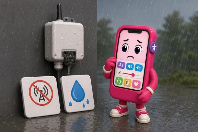
Name the field failure that would make the device useless.
-
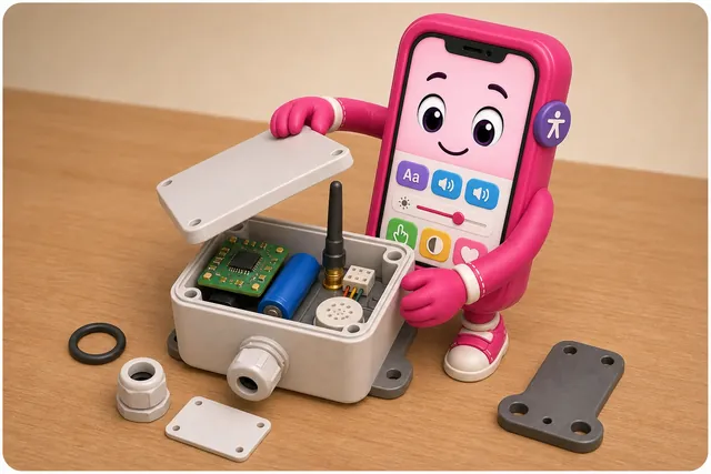
Place every working, sealing, radio, and service part in one real mock-up.
-
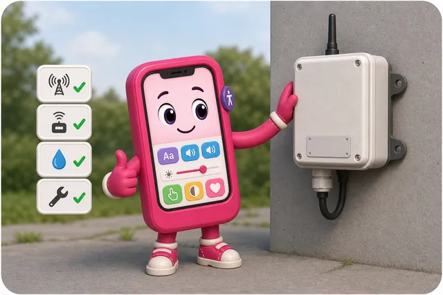
Test the closed device in its installed pose and save concrete results.
First, the wet site raises water-entry and blocked-radio risks. Next, the open mock-up shows a board, antenna, battery, cable entry, loose seal, cover, and mount. Last, the closed case is checked in its installed position for signal, sensing, water entry, and service access. That order turns a shape choice into field evidence.
Start with the failure that would make the device useless in the field. A LoRaWAN sensor in a metal cabinet may need an external SMA antenna or a plastic RF window. A BLE asset tag on a wet pallet may need antenna clearance from liquid and metal. A greenhouse controller may need DIN-rail mounting, cable strain relief, IP-rated glands, and clear local status because workers troubleshoot it without a laptop.
Run the review as a walk-through of the installed life of the device. Put the board, antenna, battery, connector, sensor opening, seal, label, and mounting hardware into the same drawing or physical mock-up. Then ask who touches each part during commissioning, battery replacement, cleaning, reset, calibration, ownership transfer, and disposal. If the installer needs to scan a QR code, the code must remain visible after mounting. If the device uses a reset pinhole, the tool must be available in the service context. If the sensor needs airflow, the mounting bracket cannot block the vents.
Keep the evidence concrete. For RF, record RSSI, SNR, packet-loss, or throughput checks with the enclosure closed and mounted in the expected orientation. For sensing, record response tests with the real membrane, lens, acoustic port, probe length, or airflow path. For ingress, record which opening, gasket, cable gland, button, or battery door is the weak point. For service, record how long the maintenance action takes, what tool it requires, and what error is easy to make under realistic conditions.
- Map the installed envelope. Include board outline, battery chemistry, connector bend radius, sensor keepout, antenna keepout, wall thickness, screws, clips, seals, labels, and the tool path for assembly.
- Select material and protection. Compare PC/ABS, polycarbonate, aluminum, TPU, silicone gaskets, vent membranes, conformal coating, and potting against radio, heat, cleaning, repair, and ingress needs.
- Test the actual orientation. Check RSSI/SNR or packet loss with the cover closed, sensor response through the installed opening, charging or battery access, LED visibility, button reach, and whether the mount survives vibration or impact.
Ratings and prototypes need context. IP54, IP65, IP67, IK impact ratings, UL enclosure materials, and 3D-printed prototype checks are useful only when they match the real exposure, maintenance interval, and installation orientation.
The review should end with an accepted tradeoff, not a vague approval. A sealed sensor might reject field battery replacement to improve washdown reliability, but then the product needs a replacement plan and low-battery warning. A wearable might accept a smaller cell to reduce pressure points, but then the charging habit must fit the user’s day. A metal enclosure might be justified for impact and heat, but only with an antenna plan that has been tested after assembly. Those tradeoffs are design decisions; they should have an owner and a condition for another review.