Lab 3: Antenna Placement Tests
Lab 3: Antenna Placement Tests
Lab 3: Antenna Placement Tests
Antenna placement is a test variable, not a decoration. Change one placement factor at a time and keep the tag set fixed while you compare outcomes.
Use this sequence:
When a placement improves one scenario but creates stray reads in another, record both effects. The correct result may be a narrower read zone, a second antenna, a different tag mount, or a workflow change that prevents ambiguous reads.
Figure 1 turns the preceding test variables into an ordered comparison. Follow the workflow from a recorded baseline through boundary, orientation, and material checks before accepting one documented change.
Figure 1 makes each antenna adjustment a controlled retest.
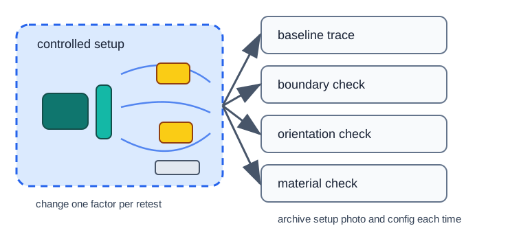
The placement workflow in Figure 1 begins with a photographed baseline and a trace from the standard tag set. Keep reader settings, dwell rule, and scenario order fixed. Boundary tags test unwanted reach; rotated tags expose coupling changes; metal, liquid, dense packaging, and handling test realistic detuning or blockage. Only after those checks should one antenna position or aim change. Repeat the same scenarios and archive the new setup photo, settings, and traces. A better count after several simultaneous changes cannot show which one helped, and an improved target read may still enlarge the unwanted zone.
In the workflow diagram Figure 1, the baseline fixes the geometry and reader configuration that later runs must share. The boundary check tests unwanted reach, the orientation check exposes coupling changes, and the material check introduces realistic detuning or blockage. Only after those observations does the change record permit one controlled adjustment and a repeated run. This sequence keeps a better result attributable to a specific placement change rather than to several moving variables.
The workflow becomes concrete in Figure 2, where a real doorway antenna, bracket, cable, and surrounding structure show what a “10 cm move” actually alters.
The doorway antenna in Figure 2 shows the mount and cable path that the lab must record.

Start with a baseline trace from the installed antenna before changing its height, angle, or power. Walk expected tags through the doorway, then place boundary tags nearby to test unwanted reads. Change one factor, repeat the same paths and orientations, and compare raw observations and filtered events. Keep a setup photo, reader configuration, and cable condition with both runs so the cause of any difference remains visible. The photograph shows a real installation, but it cannot establish read-zone coverage or isolation without those site traces.
In Figure 2, begin at the mounted antenna face, then inspect its bracket and cable route, and finally consider the doorway and nearby equipment that bound the field. A re-aim changes polarization and coverage; a move changes distance and multipath; disturbed cabling can change loss or service reliability. The photograph connects the controlled workflow in Figure 1 to the installed object that must be photographed, measured, traced, and retested.
Photo: Geirvevle, CC BY-SA 3.0.
