Pitfall: Inadequate Heat Sink Design for Motor Drivers
Pitfall: Inadequate Heat Sink Design for Motor Drivers
animation
actuators
safety
Try Keep Voltage drop (V) at 2 and Motor current (A) at 2, then lower Duty cycle from 1.
Observe Power Dissipation starts at 4.00 W with a heat-sink message; lowering Duty cycle reduces the displayed loss.
Explain Voltage drop (V) multiplied by Motor current (A) and Duty cycle gives the average power loss.
Technical boundaries. The estimate assumes a constant driver voltage drop during conduction. The message changes above 2 W; no thermal resistance, temperature rise or warm-up time is calculated.
CautionPitfall: Inadequate Heat Sink Design for Motor Drivers
-
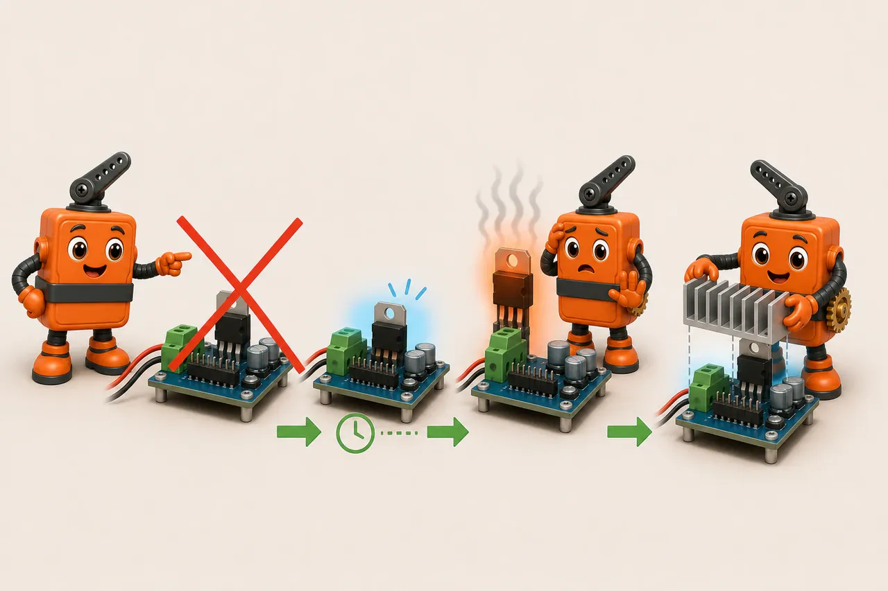
Wrong: A short test proves the driver needs no cooling. Heat can build until it shuts down.
The Mistake: Using motor driver ICs (L298N, DRV8825, TMC2209) without heat sinks or adequate thermal management, then wondering why the driver shuts down after 10-15 minutes of operation.
Why It Happens: Driver boards work fine during short bench tests. The thermal protection kicks in only after sustained operation when the junction temperature exceeds 150C.
The Fix: Always calculate driver power dissipation:
P_loss = V_drop x I_motor x duty_cycle
For L298N at 2A: P = 2V x 2A = 4W
Mount adequate heat sinks (thermal resistance < 10C/W for high-current applications). Use modern MOSFET drivers (DRV8833, TB6612) with lower resistance for less heat.