Transistor low-side switching and flyback path
Study transistor switching examples from the Electronics module guide by measuring the NPN base path, load current, and inductive turn-off voltage.
Predict the base-drive effect before comparing the load and turn-off scope readouts.
Predict the reading, then compare it with the measurement.
Falstad CircuitJS
Third party ToolStudy transistor switching examples from the Electronics module guide by measuring the NPN base path, load current, and inductive turn-off voltage.
Open the prepared circuit.
Open this circuit in Falstad (new tab)Steps
Step 1
- Do
- Open the NPN low-side switch circuit on the Falstad canvas and point to the transistor with the base switch open.
- You will see
- Input: synthetic fixed-seed circuit set, seed 21. Supply: 5 V DC. Base resistor: 10 kΩ; base current 0 A. Load resistor: 300 Ω; current 497.794 pA. Transistor: Vce = 5 V.
- Why it matters
- An open base-drive path leaves essentially the whole supply across the transistor and no useful load current.
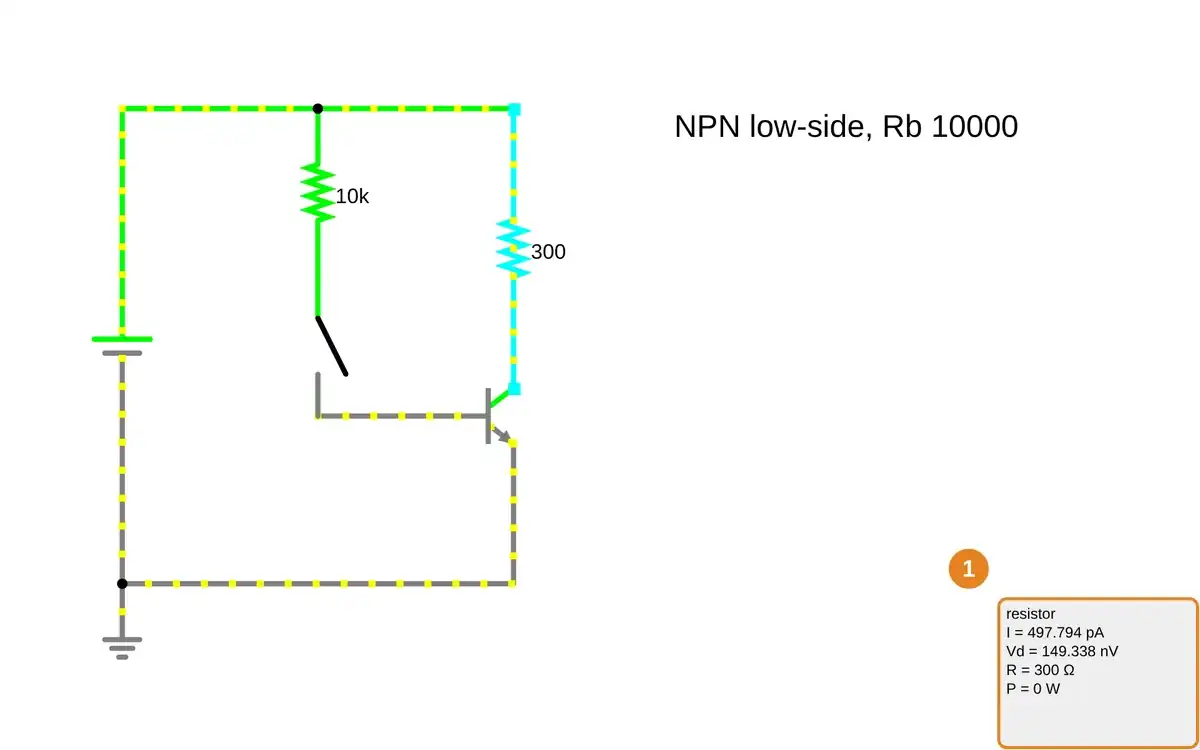
Step 1 · Falstad CircuitJS; numbered callout added to a real capture. Enlarge screenshot (new tab) Step 2
- Do
- Open the closed-switch circuit on the canvas and inspect transistor collector and base currents.
- You will see
- Base resistor: 10 kΩ. Base current: Ib = 433.14 μA. Collector current: Ic = 16.309 mA. Transistor state: saturation. Transistor Vce = 107.407 mV.
- Why it matters
- A small base current controls the 300 Ω load current without routing the load through a GPIO-like drive path.
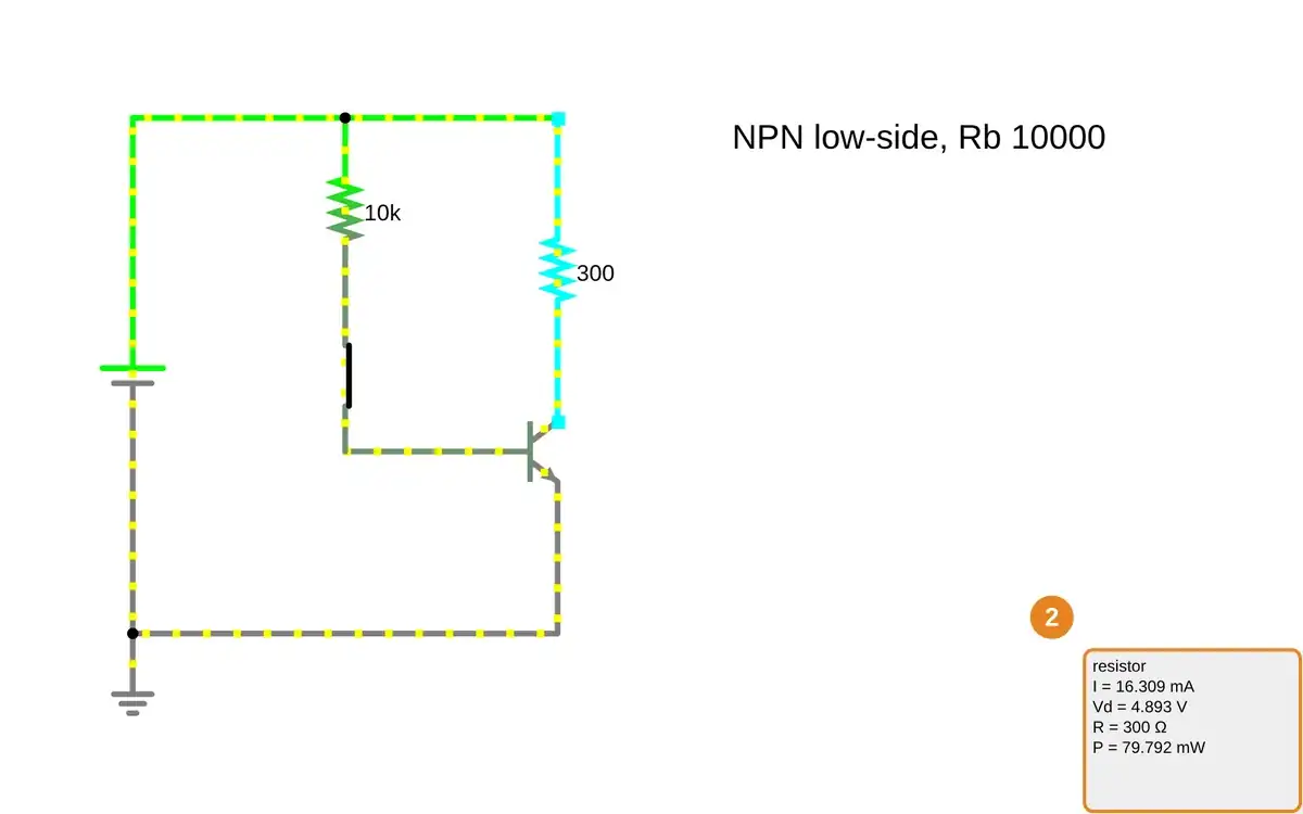
Step 2 · Falstad CircuitJS; numbered callout added to a real capture. Enlarge screenshot (new tab) Step 3
- Do
- Return to the open-switch circuit on the canvas and point to the 300 Ω load resistor.
- You will see
- Switch: open. Load resistor: R = 300 Ω. Load resistor: I = 497.794 pA. Load resistor: Vd = 149.338 nV. Transistor: Vce = 5 V.
- Why it matters
- The load returns to an effectively off state when base drive is removed; modeled leakage is not literally zero.
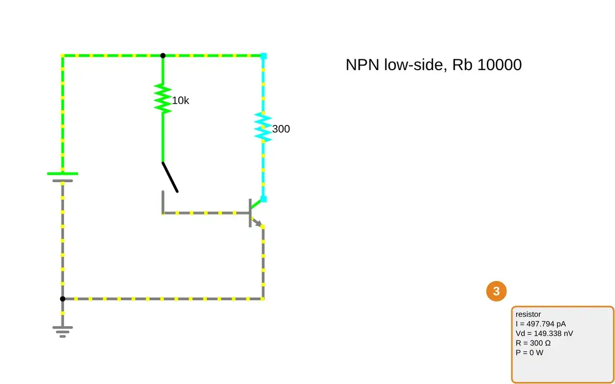
Step 3 · Falstad CircuitJS; numbered callout added to a real capture. Enlarge screenshot (new tab) Step 4
- Do
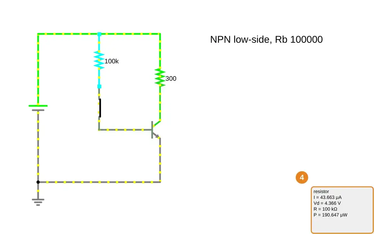
- Open the 100 kΩ base-resistor circuit on the canvas and compare its transistor readout with the 10 kΩ case.
- You will see
- Base resistor: 100 kΩ. Base current: Ib = 43.663 μA. Collector current: Ic = 4.366 mA. Transistor state: forward active. Transistor Vce = 3.69 V.
- Why it matters
- Tenfold base resistance reduces base drive and the transistor no longer reaches the earlier saturation point.
Step 4 · Falstad CircuitJS; numbered callout added to a real capture. Enlarge screenshot (new tab) Step 5
- Do
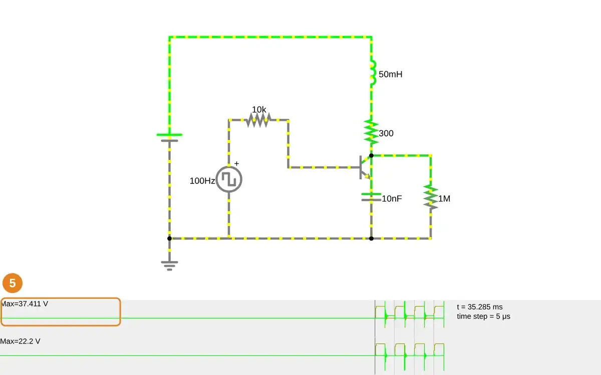
- Open the 50 mH inductive-load circuit without a diode on the canvas and inspect the switch-node voltage scope.
- You will see
- Supply: 5 V DC. Load: 50 mH and 300 Ω. Drive: 100 Hz square wave through 10 kΩ. Parasitic capacitor: 10 nF; leak: 1 MΩ. Unprotected switch-node scope: Max=37.411 V.
- Why it matters
- The modeled coil releases stored energy at turn-off; this uncontrolled circuit exceeds the supply voltage.
Step 5 · Falstad CircuitJS; numbered callout added to a real capture. Enlarge screenshot (new tab) Step 6
- Do
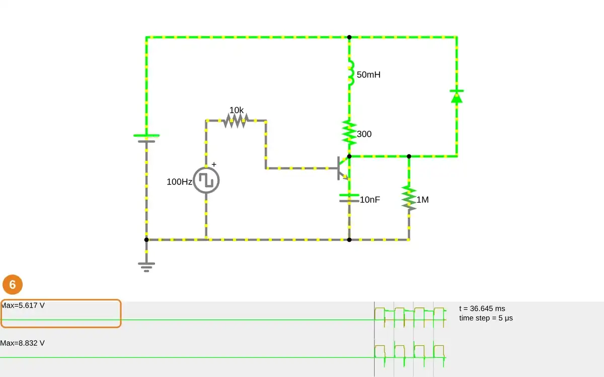
- Open the same inductive circuit with a flyback diode on the canvas and inspect the switch-node voltage scope.
- You will see
- Supply: 5 V DC. Load: 50 mH and 300 Ω. Flyback diode: across the load, anode at switch node. Protected switch-node scope: Max=5.617 V. Unprotected comparison: Max=37.411 V.
- Why it matters
- A diode return path clamps the modeled switch-node peak; this result does not establish real transistor, diode, coil, or supply ratings.
Step 6 · Falstad CircuitJS; numbered callout added to a real capture. Enlarge screenshot (new tab)
Chapter checks
These questions refer to the chapter’s examples. Use the return links to review their answers.
A plant monitor’s GPIO requests a water-valve opening. Which path should supply the valve current?
Return to the chapter’s knowledge checkAn ESP32 controls the example’s high-current LED through a transistor. What does the base resistor path provide?
Return to the chapter’s knowledge check
Return to Electronics: Power and Transistor Switching · Browse Labs