Track sensor timestamps and buffer pressure
Design bounded buffers and backpressure policies before outages or bursts occur; record event time, processing time, queue depth, and explicit sample loss.

Use the module's acquisition-timing route to design bounded buffers and record event time, processing time, queue depth, and explicit gaps before downstream analytics.
Predict the reading, then compare it with the measurement.
Wokwi ESP32
Third party ToolDesign bounded buffers and backpressure policies before outages or bursts occur; record event time, processing time, queue depth, and explicit sample loss.
Open the ESP32 editor, paste diagram.json, then paste sketch.ino.
Open Wokwi to paste in the files (new tab)Get the files
Use both prepared files. This is a paste-in setup; saving a project requires a Wokwi account.
sketch.ino
- Use the launch button above to open the ESP32 editor in Wokwi.
- Select the editor’s diagram.json tab and replace all its text with the supplied diagram.json.
- Select the sketch.ino tab, replace all its text with the supplied sketch.ino, then click Start Simulation.
Steps
Step 1
- Do
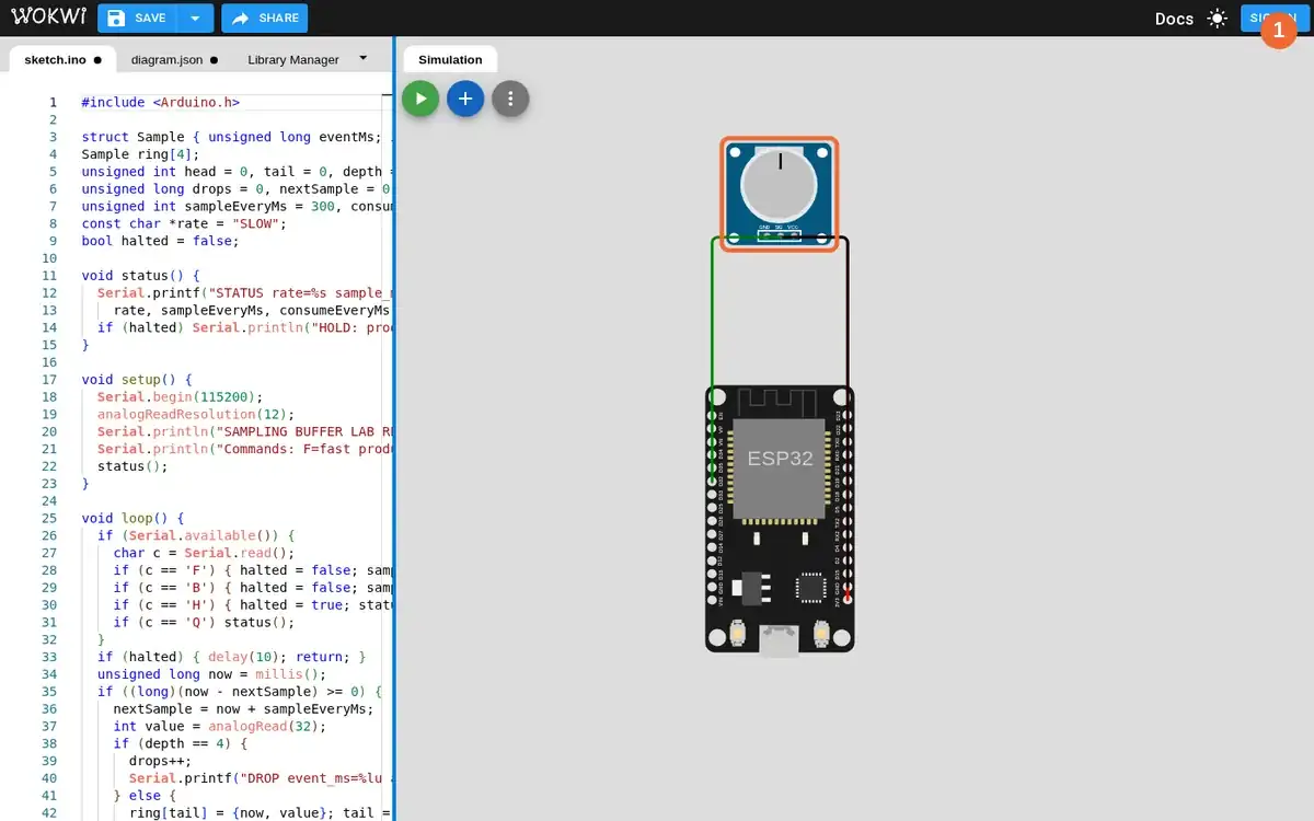
- In the Wokwi editor, paste the supplied diagram and sketch and inspect the virtual potentiometer and four-slot ring buffer before starting.
- You will see
- Input: loaded the ESP32 and Wokwi virtual potentiometer in the public editor. Observed: the virtual sensor's signal connects to ESP32 GPIO32 and starts at knob setting 512/1023. Observed: the visible sketch declares `Sample ring[4]` and a dropped-sample counter. Observed: the stopped Simulation panel had no sample lines yet.
- Why it matters
- The potentiometer is a simulated sensor input, not a physical measurement. A four-slot queue makes pressure and overflow visible quickly. The sketch stores an event timestamp with each sample. The stopped view establishes the configured source before any queue result.
Step 1 · Wokwi ESP32; numbered callout added to a real capture. Enlarge screenshot (new tab) Step 2
- Do
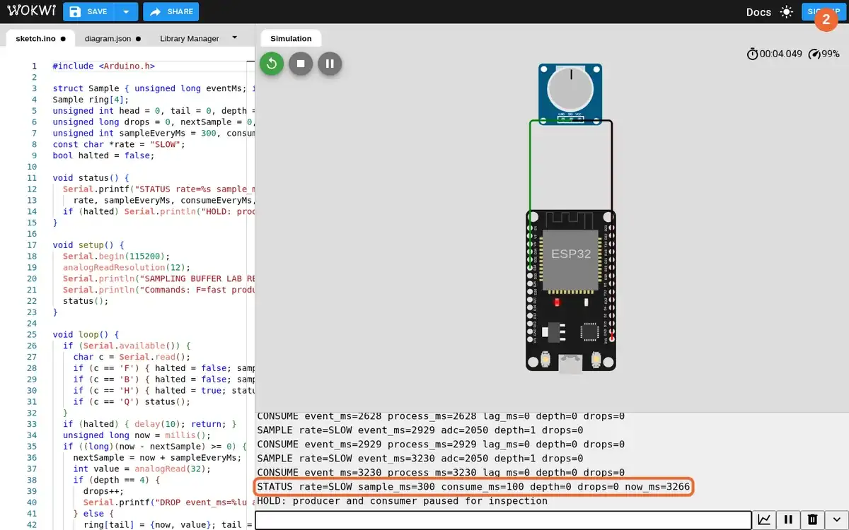
- In the Simulation panel, start Wokwi at the slow 300 ms sampling rate and inspect Serial Monitor before pausing with H.
- You will see
- Input: ran the virtual sensor with 300 ms sampling and 100 ms consumption, then sent `H` to pause for inspection. Observed: `SAMPLE rate=SLOW event_ms=3230 adc=2050 depth=1 drops=0`. Observed: `CONSUME event_ms=3230 process_ms=3230 lag_ms=0 depth=0 drops=0`. Observed: `STATUS rate=SLOW sample_ms=300 consume_ms=100 depth=0 drops=0 now_ms=3266`.
- Why it matters
- The sample carries simulator event time into the queue. The consumer reports its own processing time and measured queue lag. At this rate the consumer cleared the queue before it filled. The hold command stops both counters so the screenshot records a stable observation.
Step 2 · Wokwi ESP32; numbered callout added to a real capture. Enlarge screenshot (new tab) Step 3
- Do
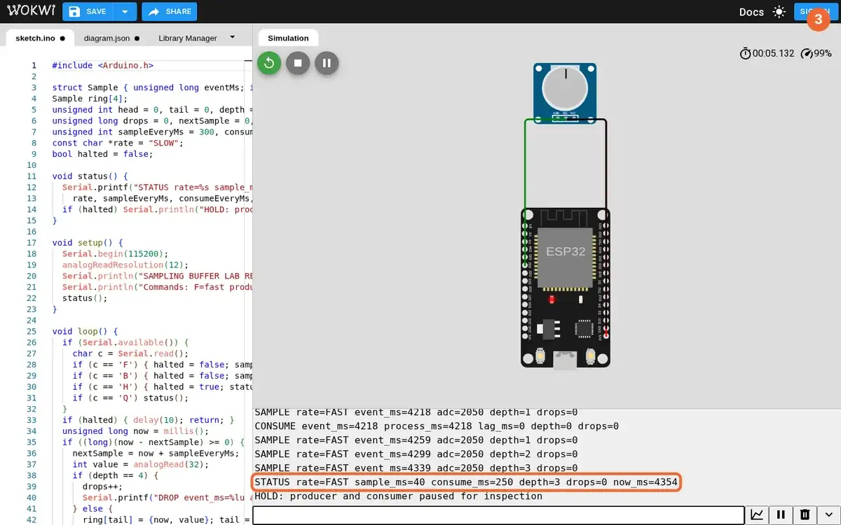
- In Serial Monitor, send F for a 40 ms producer and 250 ms consumer, then send H after depth reaches three.
- You will see
- Input: sent `F` to increase simulated sampling rate while keeping a slower consumer. Observed: `SAMPLE rate=FAST event_ms=4339 adc=2050 depth=3 drops=0`. Observed: `STATUS rate=FAST sample_ms=40 consume_ms=250 depth=3 drops=0 now_ms=4354`. Observed: the queue rose from zero to three occupied slots before the hold.
- Why it matters
- The producer now offers samples faster than the consumer removes them. The queue depth records pressure before loss begins. Event time remains attached to each sample. Holding the firmware at depth three preserves the pre-overflow state for comparison.
Step 3 · Wokwi ESP32; numbered callout added to a real capture. Enlarge screenshot (new tab) Step 4
- Do
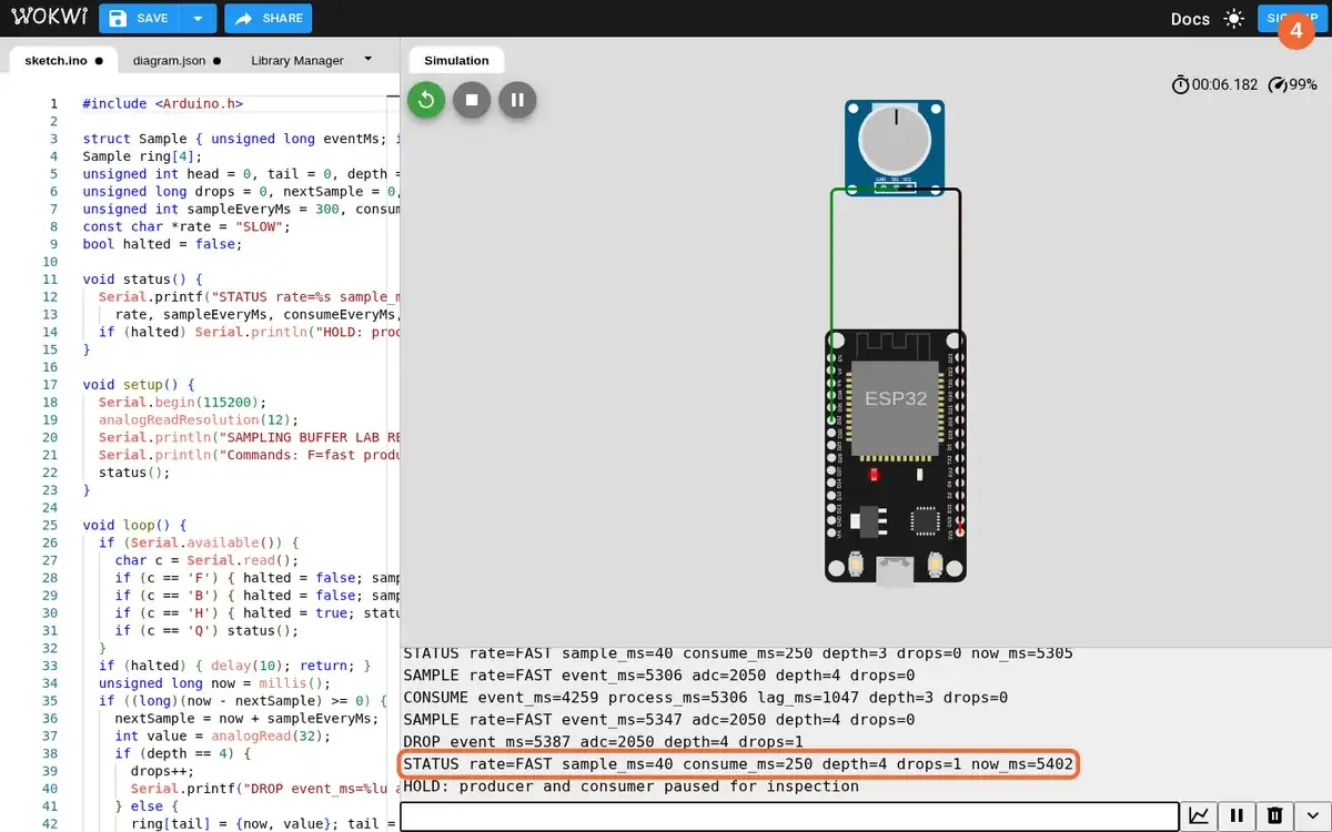
- In Serial Monitor, send F again to continue the fast producer until the first DROP line, then send H.
- You will see
- Input: resumed 40 ms sampling with the same four-slot queue. Observed: `DROP event_ms=5387 adc=2050 depth=4 drops=1`. Observed: `STATUS rate=FAST sample_ms=40 consume_ms=250 depth=4 drops=1 now_ms=5402`. Observed: a sample was explicitly discarded only after all four slots were occupied.
- Why it matters
- The ring buffer has a declared capacity of four. The DROP line carries the rejected sample's event time and sensor code. The drop counter exposes loss instead of silently overwriting data. The hold preserves the first overflow evidence before moving to recovery.
Step 4 · Wokwi ESP32; numbered callout added to a real capture. Enlarge screenshot (new tab) Step 5
- Do
- In Serial Monitor, send B to restore 300 ms sampling and 100 ms consumption; wait for the queue to drain, then send H.
- You will see
- Input: sent `B` after the full-buffer run and waited for depth zero. Observed: `CONSUME event_ms=6657 process_ms=6758 lag_ms=101 depth=0 drops=2`. Observed: `STATUS rate=BALANCED sample_ms=300 consume_ms=100 depth=0 drops=2 now_ms=6769`. Observed: the drop count stayed at two while the queue drained to zero.
- Why it matters
- The restored consumer can remove samples faster than the producer adds them. The buffered sample's 101 ms lag is distinct from its event timestamp. The historical loss remains visible as drops=2. The zero-depth hold proves recovery in this simulator run rather than assuming it from settings.
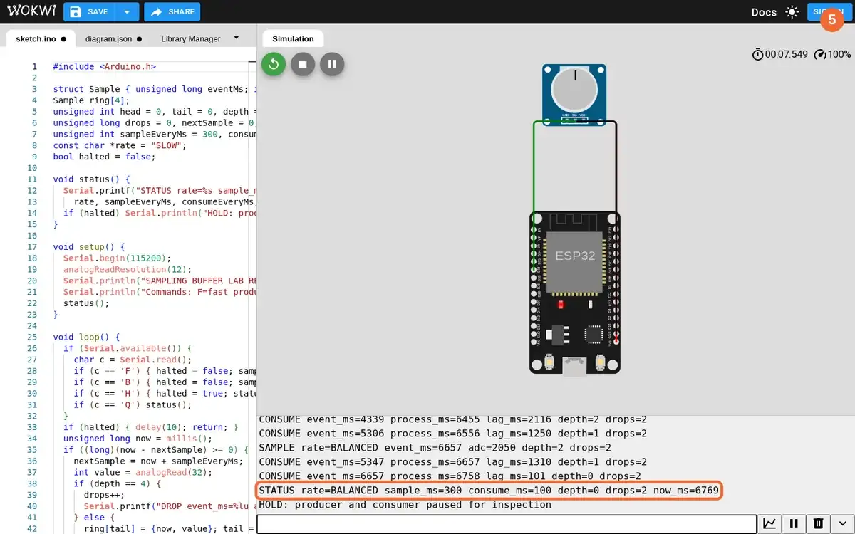
Step 5 · Wokwi ESP32; numbered callout added to a real capture. Enlarge screenshot (new tab) Step 6
- Do
- On the Wokwi circuit canvas, turn the virtual potentiometer knob to 900/1023, resume balanced rates with B, and inspect the new sample and drop count.
- You will see
- Input: moved the real simulator knob to 900/1023 and resumed balanced sampling. Observed: `SAMPLE rate=BALANCED event_ms=8172 adc=3603 depth=1 drops=2`. Observed: the matching consumer line returned depth to zero with `lag_ms=0`. Observed: `STATUS rate=BALANCED sample_ms=300 consume_ms=100 depth=0 drops=2 now_ms=8218`.
- Why it matters
- The changed virtual sensor value produced a changed ADC code. The record keeps event time, queue depth, and accumulated loss beside that reading. At the balanced rate the queue cleared and drop count did not rise further. This is a deterministic simulator observation, not a physical sensor or gateway timing claim.
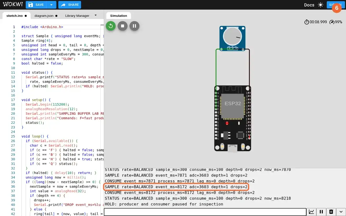
Step 6 · Wokwi ESP32; numbered callout added to a real capture. Enlarge screenshot (new tab)
Chapter checks
These questions refer to the chapter’s examples. Use the return links to review their answers.
When source clocks are synchronized and monitored, why should sensor data be timestamped at the source (event time) rather than when it arrives at the server?
Return to the chapter’s knowledge checkA gateway buffer fills during an outage. Which design keeps downstream analytics honest?
Return to the chapter’s knowledge check
Return to Acquisition Timing and Buffer Contracts · Browse Labs