Manually stop a fan after its command link fails
Observe a normal temperature command, break the fan wireless path, detect missing gateway status, and use the fan’s documented direct control to stop it manually.

Packet Pete
Predict the reading, then compare it with the measurement.
Cisco Packet Tracer
Desktop labObserve a normal temperature command, break the fan wireless path, detect missing gateway status, and use the fan’s documented direct control to stop it manually.
Install the tool; build from the steps. No file yet.
Download the Packet Tracer fileSteps
Step 1
- Do
- Open lab.pkt in the Logical workspace. Find Home Gateway0 and wired PC0. Find Temp-Monitor and Fan-Actuator. Start with Wireless0 connected and fan Off.
- You will see
- The gateway and PC are left of two wireless Things. Temp-Monitor displays a numeric temperature. Fan-Actuator is a separate output Thing. The fan icon is stationary in this reopened view.
- Why it matters
- Off is the chosen default for this demonstration. The gateway provides the normal command path. The fan is the output whose status matters. A known start state makes later failure visible.
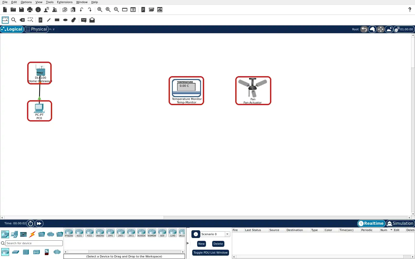
Step 1 · Cisco Packet Tracer; numbered callout added to a real capture. Enlarge screenshot (new tab) Step 2
- Do
- Open Fan-Actuator Specifications tab. Scroll to the Direct Control section. Read the Alt-click interaction instruction. Distinguish it from remote gateway control.
- You will see
- Fan is identified as a Ceiling Fan Thing. The Direct Control line says ALT-click to interact. The page separately describes MCU local control. It does not describe an automatic link-loss timeout.
- Why it matters
- Alt-click is a real operator control in this model. It offers a possible manual stop after disconnection. It requires a person at the Logical workspace. It is not proof of unattended fail-safe behaviour.
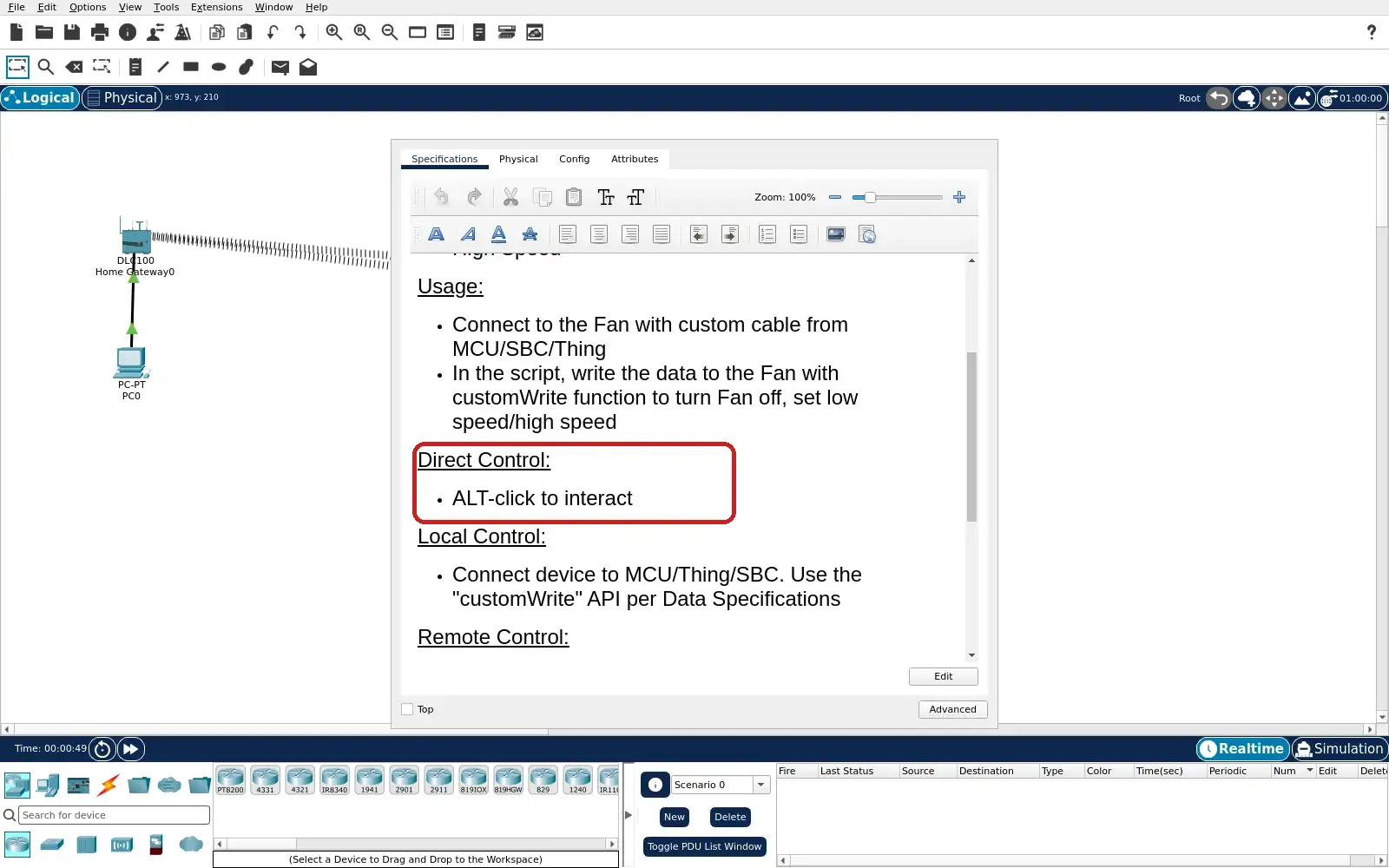
Step 2 · Cisco Packet Tracer; numbered callout added to a real capture. Enlarge screenshot (new tab) Step 3
- Do
- On PC0 open Desktop and Web Browser. Sign in at http://192.168.25.1 as admin/admin. Open the Conditions list. Read both enabled temperature rules.
- You will see
- Warm air starts fan tests Temp-Monitor > 8.0 °C. Its action sets Fan-Actuator Status High. Cool air stops fan tests temperature <= 8.0 °C. Its action sets Fan-Actuator Status Off.
- Why it matters
- These are normal gateway commands, not local interlocks. The fan receives them through its wireless link. A failed link can block the Off command. Both rules must be known before injecting failure.
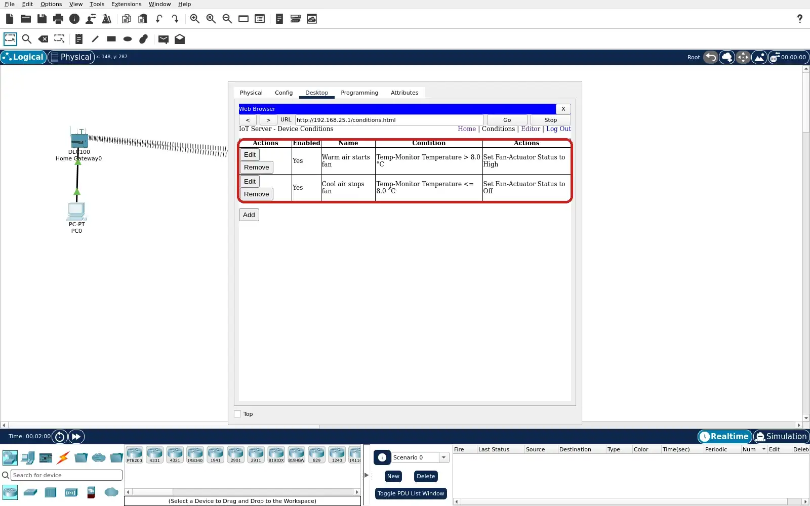
Step 3 · Cisco Packet Tracer; numbered callout added to a real capture. Enlarge screenshot (new tab) Step 4
- Do
- Open the Home device list and expand both rows. Observe a cool interval of simulated time. Read Temp-Monitor and fan Status. Record the connected baseline.
- You will see
- Temp-Monitor reads 4.3 °C in this capture. Fan-Actuator is registered with a green dot. Fan Status has Off highlighted. The displayed fan icon is stationary.
- Why it matters
- This cool state matches the gateway Off rule. The exact value can vary in another run. Registration means the device is visible to the gateway. It does not guarantee future command delivery.
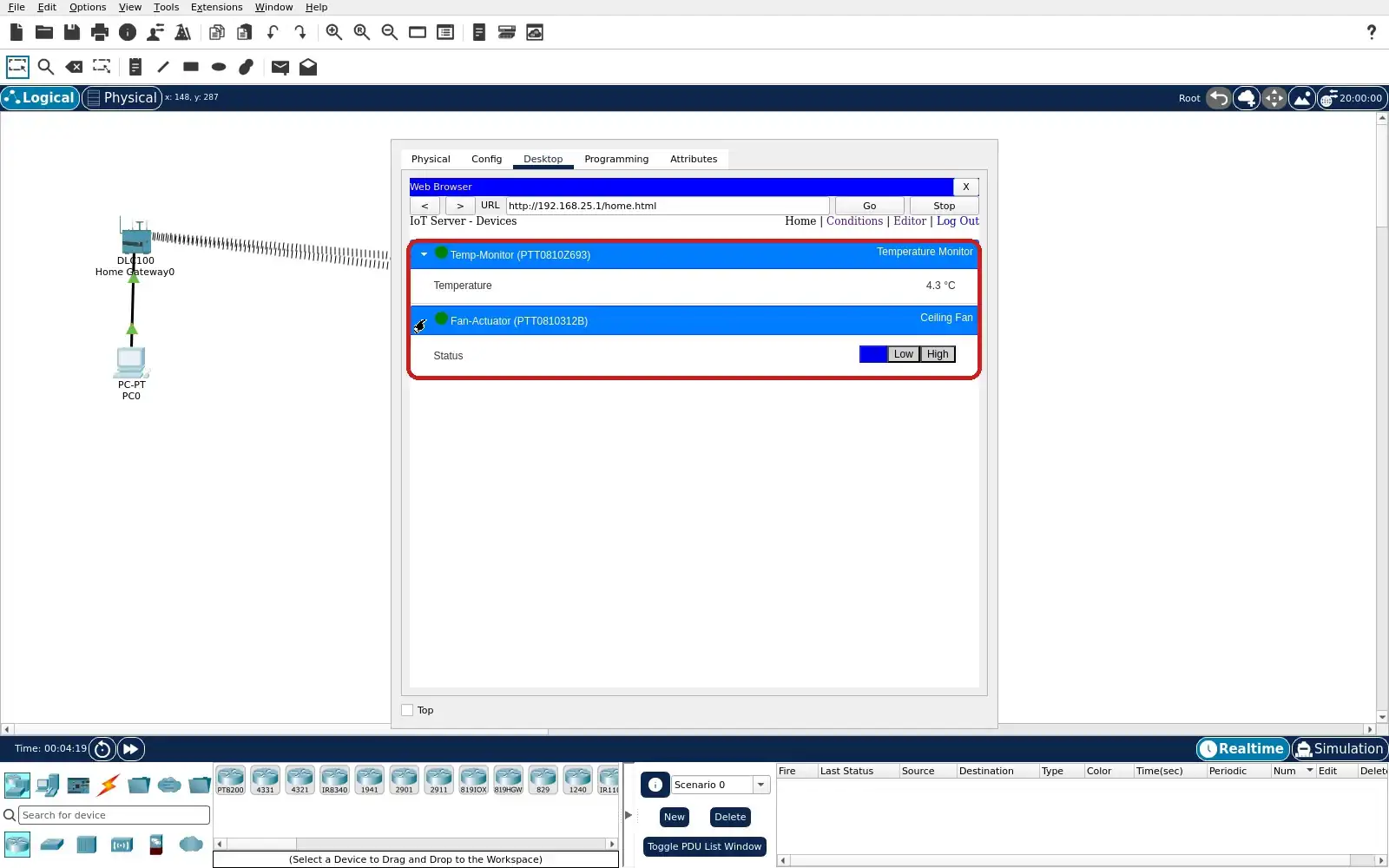
Step 4 · Cisco Packet Tracer; numbered callout added to a real capture. Enlarge screenshot (new tab) Step 5
- Do
- Keep the Home device list open as time runs. Refresh and expand both rows when needed. Find a reading above 8.0 °C. Observe the fan Status and icon.
- You will see
- Temp-Monitor reads 10.2 °C in this capture. Fan-Actuator is still registered. Fan Status has High highlighted. The fan icon shows the commanded running state.
- Why it matters
- The warm input crosses the normal High threshold. This proves the command path before it is broken. The number is simulated, not a field measurement. The next step tests whether Off can still arrive.
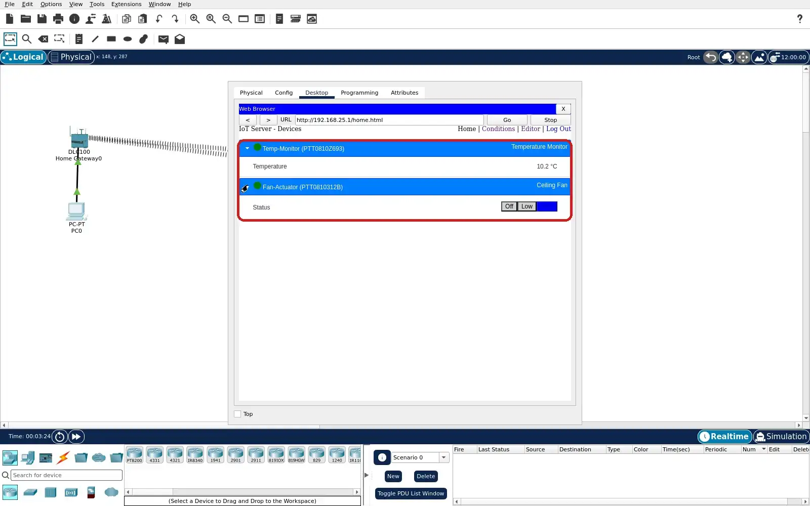
Step 5 · Cisco Packet Tracer; numbered callout added to a real capture. Enlarge screenshot (new tab) Step 6
- Do
- Open Fan-Actuator Config → Wireless0. Clear the Port Status On checkbox. Inspect the empty box and missing wireless link. Leave the gateway and Temp-Monitor connected.
- You will see
- Wireless0 Port Status On is unchecked. The fan-to-gateway wireless line disappears. The gateway-to-Temp-Monitor line remains. The fan keeps its last commanded state at first.
- Why it matters
- This action interrupts the fan command path. A later gateway Off rule cannot reach it. The checkbox is a real PT interface control. The experiment does not assert an automatic safe stop.
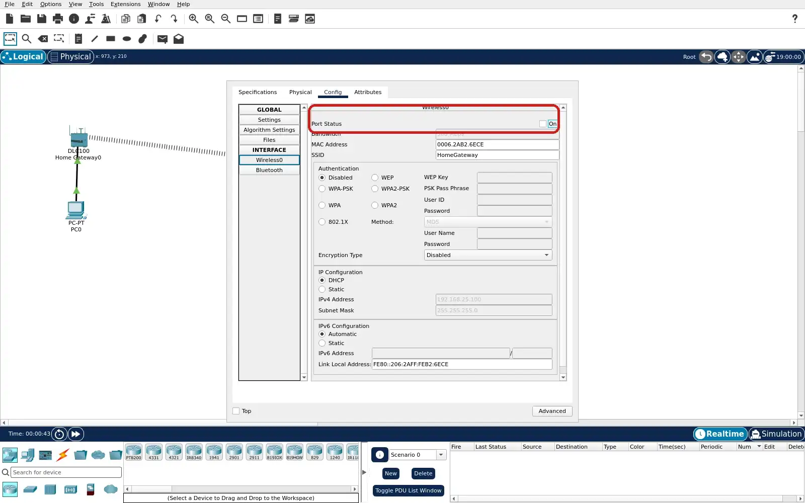
Step 6 · Cisco Packet Tracer; numbered callout added to a real capture. Enlarge screenshot (new tab) Step 7
- Do
- Refresh PC0 Web Browser Home device list. Compare it with the connected Home capture. Look for Fan-Actuator registration. Treat missing status as a fault signal.
- You will see
- Temp-Monitor remains listed with a green dot. Fan-Actuator no longer appears in Home. The browser provides no current fan Status. The fan can still be seen on the Logical workspace.
- Why it matters
- The missing row detects the command-path problem. It does not itself switch the fan Off. An operator must inspect the local output. A stale last command is a real control risk here.
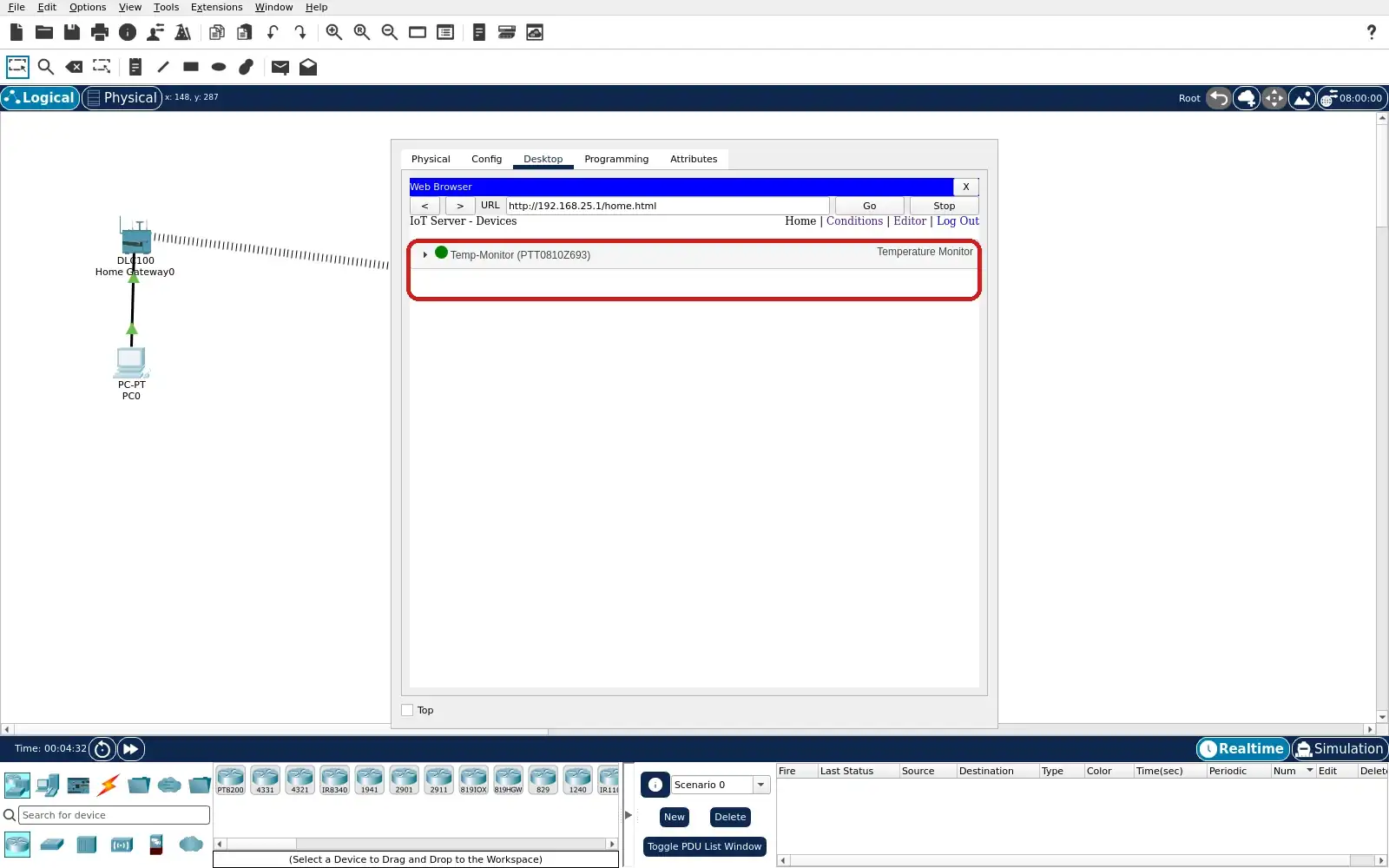
Step 7 · Cisco Packet Tracer; numbered callout added to a real capture. Enlarge screenshot (new tab) Step 8
- Do
- Close PC0 and use the Logical workspace. Alt-click the fan until its blades stop. Watch it again while the temperature varies. Reopen lab.pkt to restore the connected start state.
- You will see
- One Alt-click stopped the fan from High in this run. At 12.44 °C the fan icon is stationary. Wireless0 remained disconnected during this capture. There is no automatic timeout shown in the project.
- Why it matters
- The stop was an explicit operator action. A warm reading did not restart the disconnected fan. Manual response is narrower than fail-safe design. PT does not prove electrical isolation or physical safety.
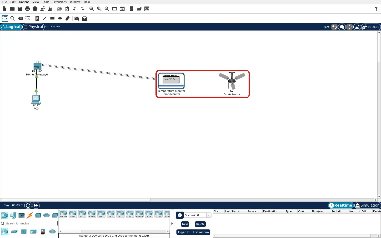
Step 8 · Cisco Packet Tracer; numbered callout added to a real capture. Enlarge screenshot (new tab)
Chapter checks
These questions refer to the chapter’s examples. Use the return links to review their answers.
A factory sensor loses its network link. Which behavior best shows graceful degradation?
Return to the chapter’s knowledge checkA heating relay loses controller power. How should its default state be chosen?
Return to the chapter’s knowledge check
Return to Actuator Safety: Protection and Fail-Safe Design · Browse Labs