Test an ESP32 pull-up button input
Configure GPIO pins for digital output, digital input, and pull-up button input; use serial output as an evidence stream for the active-low LED response.
Use this button build-test cycle to record the pin mode, the observed press and release levels, and the output condition before trusting a GPIO prototype.
Predict the reading, then compare it with the measurement.
Wokwi ESP32
Third party ToolConfigure GPIO pins for digital output, digital input, and pull-up button input; use serial output as an evidence stream for the active-low LED response.
Open the ESP32 editor, paste diagram.json, then paste sketch.ino.
Open Wokwi to paste in the files (new tab)Get the files
Use both prepared files. This is a paste-in setup; saving a project requires a Wokwi account.
sketch.ino
- Use the launch button above to open the ESP32 editor in Wokwi.
- Select the editor’s diagram.json tab and replace all its text with the supplied diagram.json.
- Select the sketch.ino tab, replace all its text with the supplied sketch.ino, then click Start Simulation.
Steps
Step 1
- Do
- In the Wokwi editor, paste the supplied diagram and sketch, then inspect the button, LED, and ESP32 wiring before starting.
- You will see
- Input: loaded the supplied diagram and sketch in the public Wokwi ESP32 editor. Observed: the blue button connects GPIO13 to ground when pressed. Observed: GPIO2 drives the green LED through a 220 Ω resistor. Observed: the Simulation panel showed the Start control and the LED was dark.
- Why it matters
- The button has no external resistor, so idle behavior depends on input mode. The ground connection makes a press a LOW input. The LED gives a visible output for the firmware condition. The stopped simulator is a wiring baseline, not an input reading.
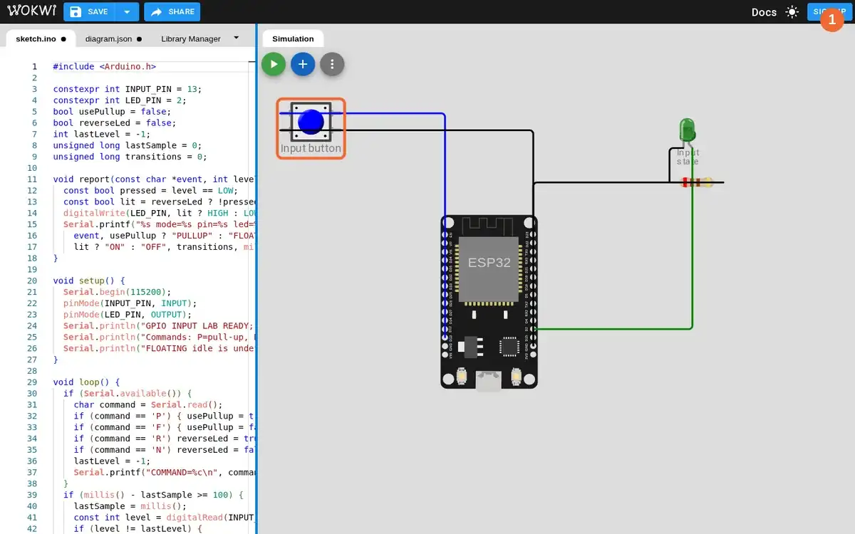
Step 1 · Wokwi ESP32; numbered callout added to a real capture. Enlarge screenshot (new tab) Step 2
- Do
- In the Simulation panel, start Wokwi with GPIO13 configured as INPUT and read the first Serial Monitor line.
- You will see
- Input: started the sketch with GPIO13 in INPUT mode and did not press the button. Observed: the running simulation clock reached 00:02.649. Observed Serial Monitor: `EDGE mode=FLOATING pin=HIGH led=OFF transitions=0 t_ms=512`. Observed: the LED was dark in this one simulator run.
- Why it matters
- The serial line is a real reading from the running simulator. With no pull-up, an unpressed pin has no defined electrical idle level. This simulator happened to resolve it HIGH; that is not a guarantee of stability on hardware. The LED state follows this sketch's active-low condition.
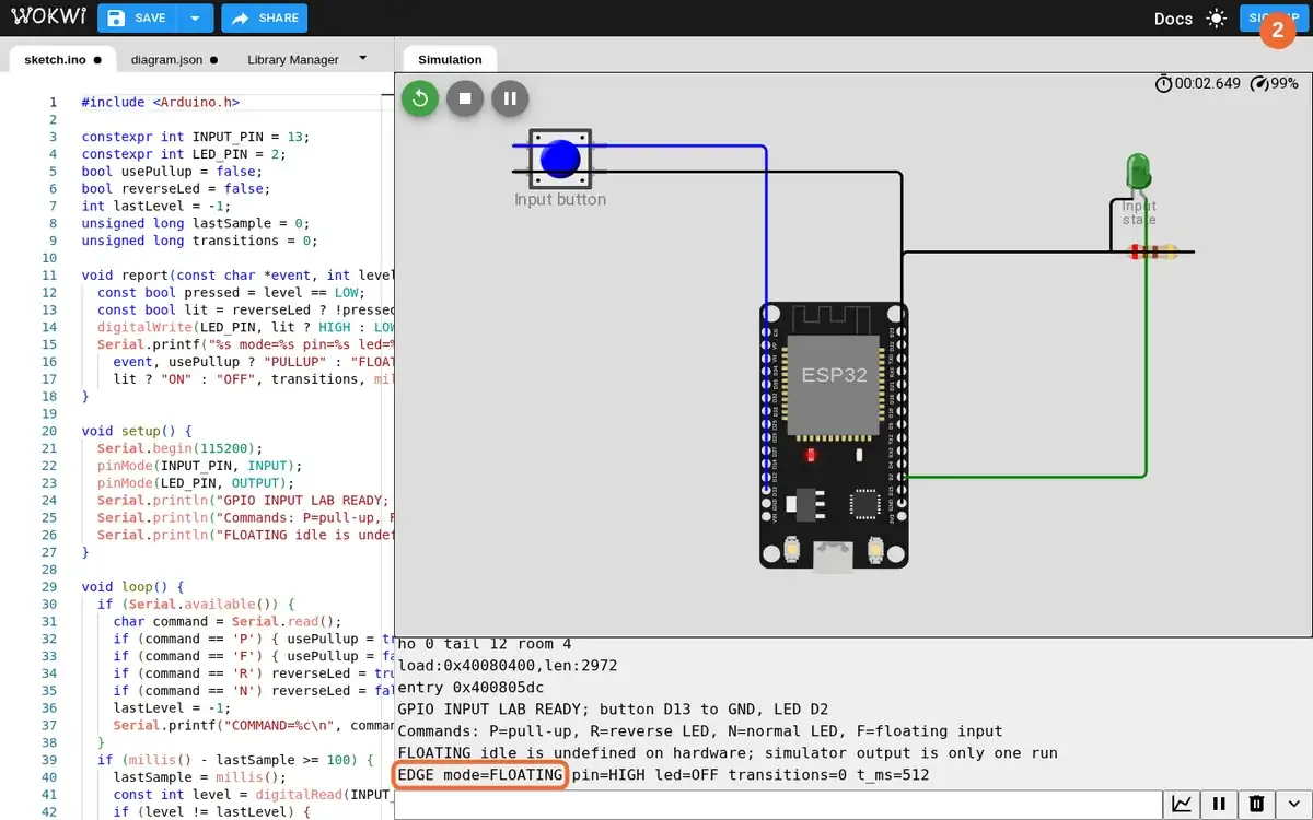
Step 2 · Wokwi ESP32; numbered callout added to a real capture. Enlarge screenshot (new tab) Step 3
- Do
- In the Serial Monitor input field, send P to enable INPUT_PULLUP, then inspect the idle line.
- You will see
- Input: sent `P` in the real Wokwi Serial Monitor. Observed: Serial Monitor printed `COMMAND=P`. Observed: `EDGE mode=PULLUP pin=HIGH led=OFF transitions=0 t_ms=2912`. Observed: the green LED remained dark while the button was released.
- Why it matters
- The command changes GPIO13 to INPUT_PULLUP in the running sketch. The internal pull-up defines a released HIGH level. The active-low LED rule keeps the output off for that HIGH. The next step tests the LOW state by pressing the grounded button.
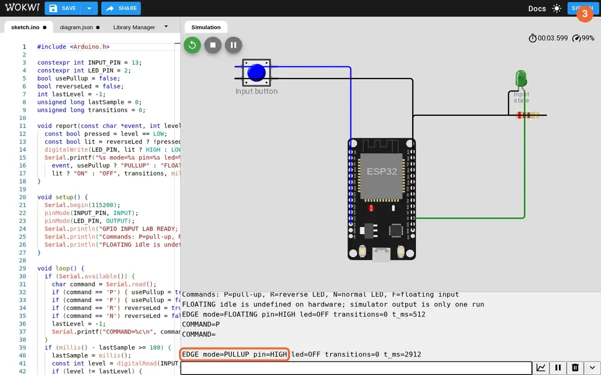
Step 3 · Wokwi ESP32; numbered callout added to a real capture. Enlarge screenshot (new tab) Step 4
- Do
- On the Wokwi circuit canvas, press and release the blue button ten times, then inspect the transition count in Serial Monitor.
- You will see
- Input: clicked the real simulated button ten times after enabling the pull-up. Observed: a LOW press line and a HIGH release line appeared for each click. Observed final line: `EDGE mode=PULLUP pin=HIGH led=OFF transitions=20 t_ms=7612`. Observed: the LED returned to dark after the tenth release.
- Why it matters
- Each complete press-release cycle has two electrical edges. Ten cycles produced 20 counted transitions in this run. The final HIGH confirms the button returned to its pulled-up idle state. The LED output returned to the original active-low idle response.
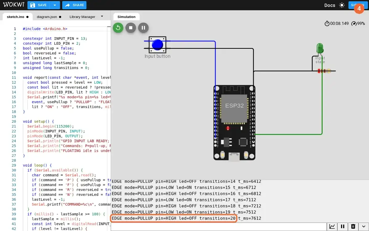
Step 4 · Wokwi ESP32; numbered callout added to a real capture. Enlarge screenshot (new tab) Step 5
- Do
- In Serial Monitor, send R to reverse only the LED condition; press the button once on the circuit canvas and read its LOW line.
- You will see
- Input: sent `R`, then clicked the button once. Observed: Serial Monitor printed `COMMAND=R`. Observed: `EDGE mode=PULLUP pin=LOW led=OFF transitions=21 t_ms=8812`. Observed: the input still read LOW on a press while the green LED was dark.
- Why it matters
- The pull-up input did not change electrical meaning. The firmware condition alone reversed the LED output. LOW still identifies the grounded pressed state. Separating pin reading from output policy prevents a false wiring diagnosis.
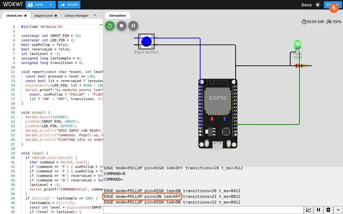
Step 5 · Wokwi ESP32; numbered callout added to a real capture. Enlarge screenshot (new tab) Step 6
- Do
- In Serial Monitor, send N to restore the normal LED condition, then press the button on the circuit canvas once more.
- You will see
- Input: sent `N`, then clicked the same grounded button. Observed: Serial Monitor printed `COMMAND=N`. Observed: `EDGE mode=PULLUP pin=LOW led=ON transitions=23 t_ms=10212`. Observed: the green LED lit during the LOW press and went dark on release.
- Why it matters
- The restored rule lights the LED for a grounded press. The input remains active-low with INPUT_PULLUP. The press after reversal added another pair of transitions. The final state matches the committed sketch's normal LED condition.
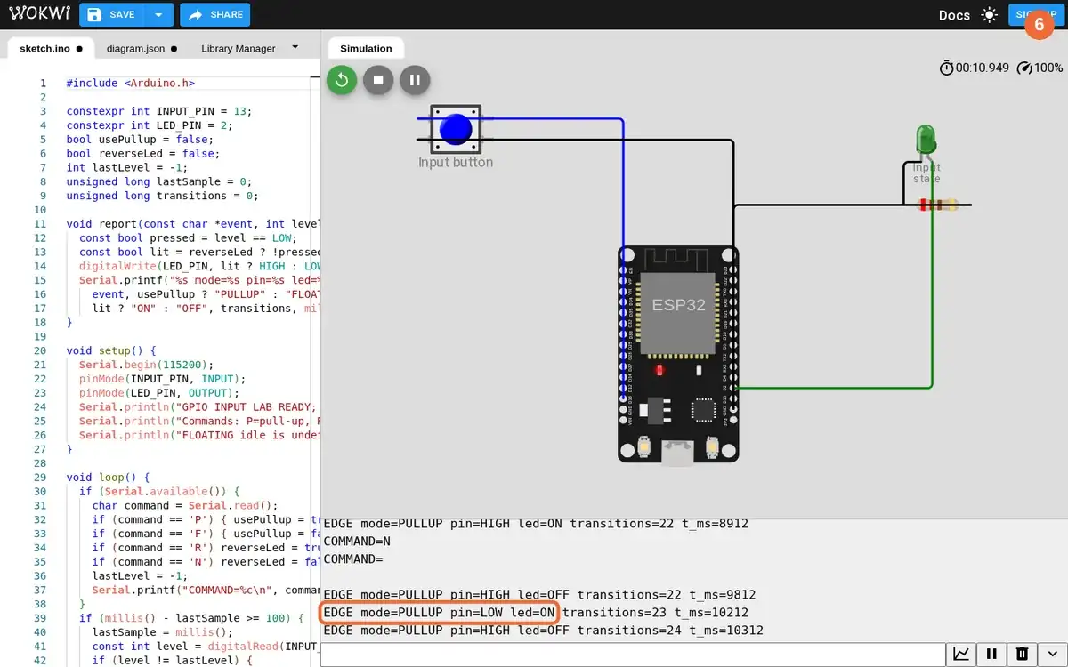
Step 6 · Wokwi ESP32; numbered callout added to a real capture. Enlarge screenshot (new tab)
Chapter checks
These questions refer to the chapter’s examples. Use the return links to review their answers.
A button uses an internal pull-up input. What reading should firmware expect when the button closes to ground?
Return to the chapter’s knowledge checkIn Arduino-style firmware, where should pin setup and repeated sensor checks go?
Return to the chapter’s knowledge check
Return to Microcontroller Programming: Setup and GPIO · Browse Labs