Diode forward and reverse conduction
Study diode forward and reverse bias, as linked in the Electronics module guide, by measuring current and voltage in both orientations.
Predict the resistor current for each polarity, then inspect the simulator readouts.
Predict the reading, then compare it with the measurement.
Falstad CircuitJS
Third party ToolStudy diode forward and reverse bias, as linked in the Electronics module guide, by measuring current and voltage in both orientations.
Open the prepared circuit.
Open this circuit in Falstad (new tab)Steps
Step 1
- Do
- Open the prepared circuit on the Falstad canvas. Inspect the 5 V source and the 1 kΩ series resistor before following the forward diode path.
- You will see
- Input: synthetic controlled circuit set, seed 9. Source: 5 V DC. Resistor: R = 1 kΩ. Resistor: I = 4.474 mA. Resistor: Vd = 4.474 V. Diode path: current flows from source through resistor to ground.
- Why it matters
- The resistor limits forward current; the model uses the remaining supply voltage across the diode.
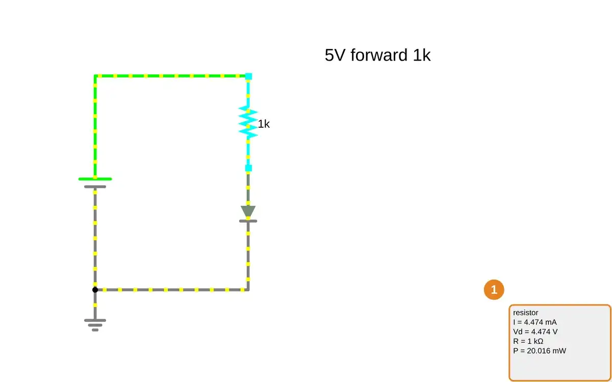
Step 1 · Falstad CircuitJS; numbered callout added to a real capture. Enlarge screenshot (new tab) Step 2
- Do
- Point to the forward diode on the circuit canvas and compare its readout with the resistor current.
- You will see
- Diode: I = 4.474 mA. Diode: Vd = 526.074 mV. Diode: P = 2.354 mW. Resistor: I = 4.474 mA. Source: Vd = 5 V.
- Why it matters
- The same current passes through both series components; the diode model has a voltage drop, not a fixed universal 0.7 V.
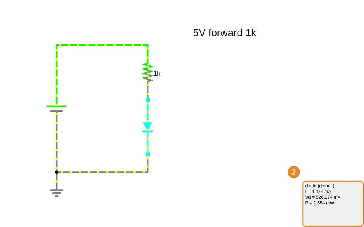
Step 2 · Falstad CircuitJS; numbered callout added to a real capture. Enlarge screenshot (new tab) Step 3
- Do
- Open the reverse-orientation circuit on the canvas and point to the diode readout.
- You will see
- Supply: 5 V DC, diode reversed. Diode: I = -171.435 nA. Diode: Vd = -5 V. Resistor: I = 171.435 nA. Resistor: Vd = 171.435 μV.
- Why it matters
- The reverse current is tiny beside 4.474 mA forward current. The model still reports nonzero leakage.
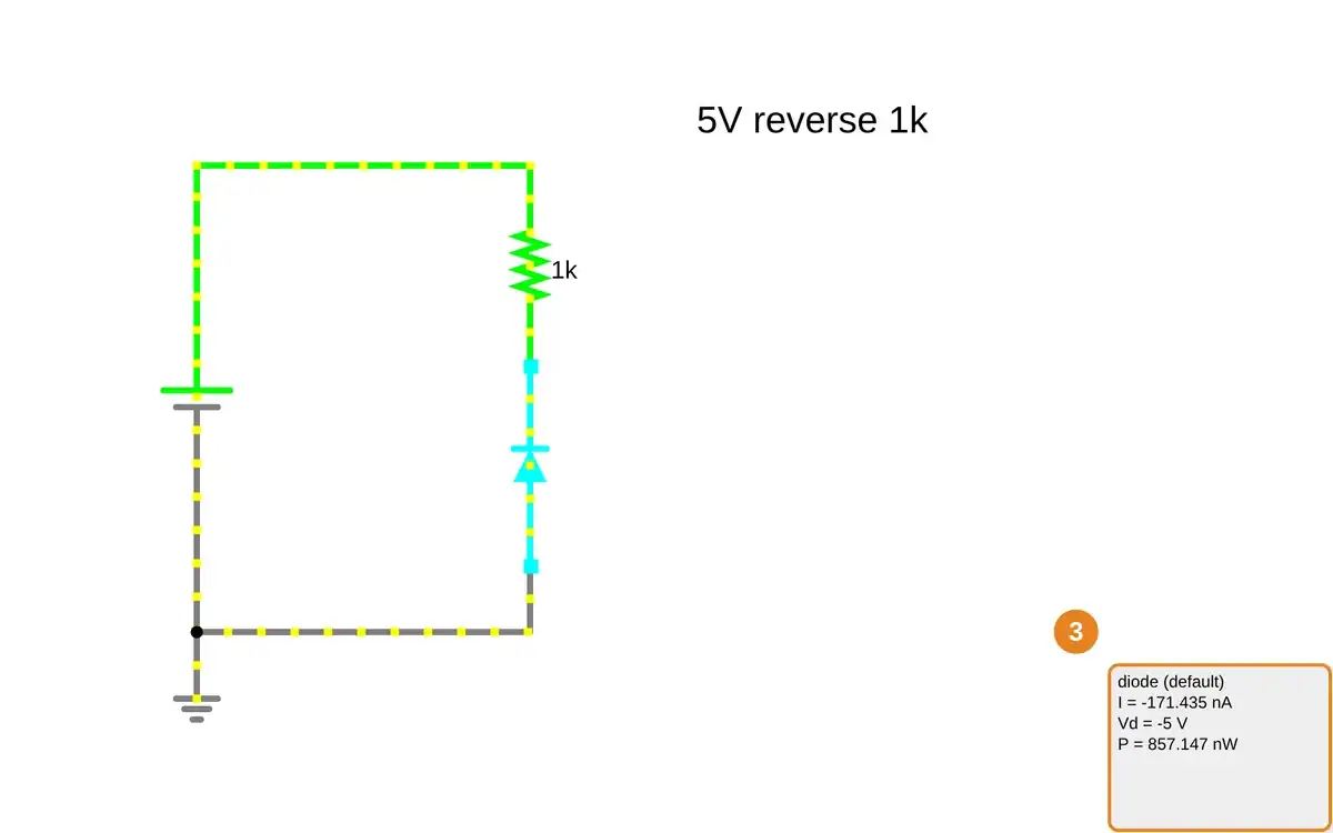
Step 3 · Falstad CircuitJS; numbered callout added to a real capture. Enlarge screenshot (new tab) Step 4
- Do
- Open the 10 V reverse-bias circuit on the canvas and inspect the source while the diode remains reversed.
- You will see
- Source: Vd = 10 V. Source: I = 171.435 nA. Diode orientation: reverse. Earlier 5 V reverse case: I = 171.435 nA. No modeled breakdown is visible in these two runs.
- Why it matters
- A larger reverse source magnitude in this model did not create forward-scale current; this is not a physical breakdown rating.
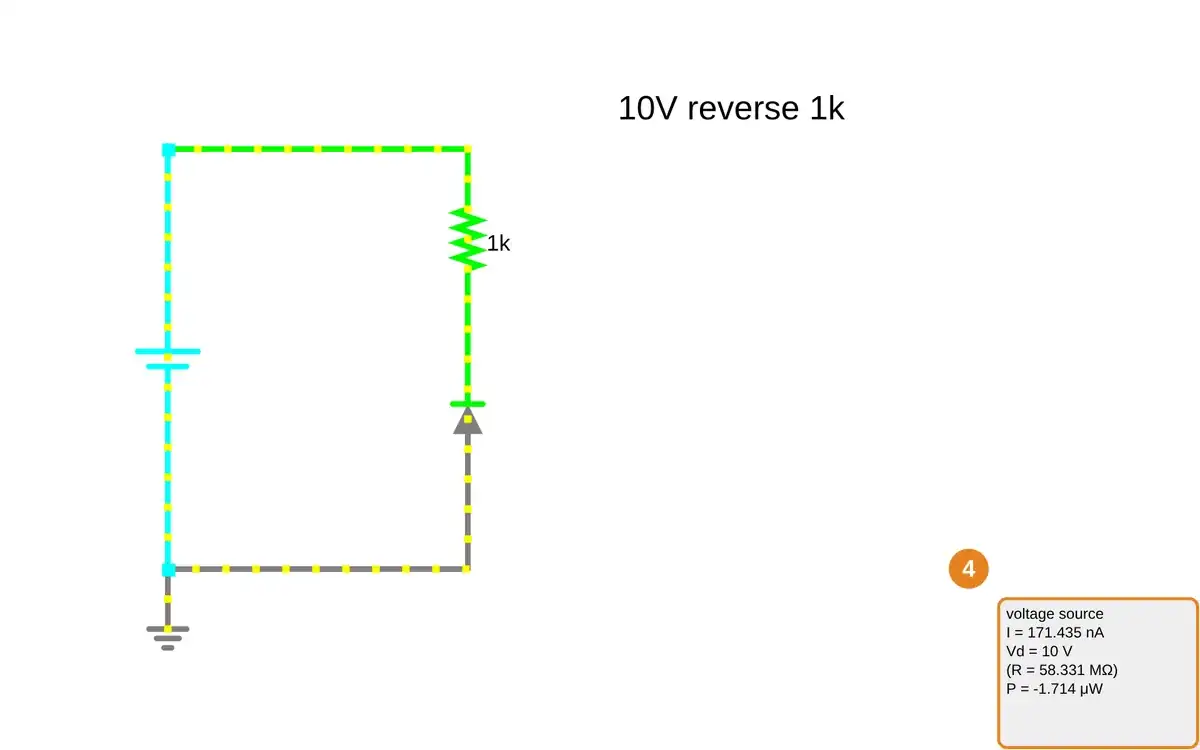
Step 4 · Falstad CircuitJS; numbered callout added to a real capture. Enlarge screenshot (new tab) Step 5
- Do
- Open the forward circuit with a 2 kΩ series resistor and point to the resistor readout on the canvas.
- You will see
- Source: 5 V DC. Resistor: R = 2 kΩ. Resistor: I = 2.255 mA. Resistor: Vd = 4.509 V. Diode: Vd = 490.628 mV.
- Why it matters
- Doubling the resistor lowered current from 4.474 mA to 2.255 mA without reversing the diode.
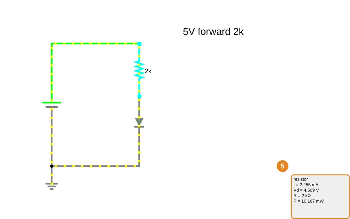
Step 5 · Falstad CircuitJS; numbered callout added to a real capture. Enlarge screenshot (new tab) Step 6
- Do
- Restore the original 5 V forward circuit on the canvas and inspect the diode readout against the reverse case.
- You will see
- Forward: I = 4.474 mA. Forward: diode Vd = 526.074 mV. Reverse at 5 V: |I| = 171.435 nA. Forward resistor: R = 1 kΩ. The complete circuit is visible with the numeric readout.
- Why it matters
- The simulation demonstrates a strong polarity contrast, but does not establish actual diode tolerances or breakdown behavior.
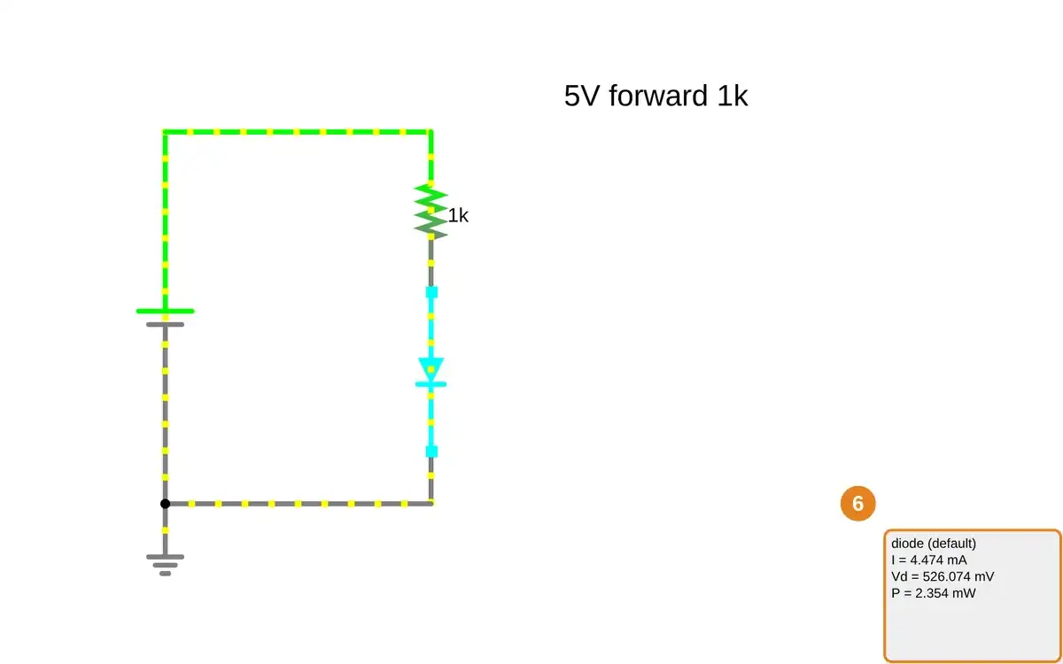
Step 6 · Falstad CircuitJS; numbered callout added to a real capture. Enlarge screenshot (new tab)
Chapter checks
These questions refer to the chapter’s examples. Use the return links to review their answers.
Which carrier becomes abundant when silicon is doped as N-type rather than P-type?
Return to the chapter’s knowledge checkThe example diode is connected with its N-side positive relative to its P-side. What behavior should the learner expect within its rating?
Return to the chapter’s knowledge check