21 Signed Sensor Decoding Contracts
21.1 Start Simple
Imagine a temperature register that says 0xFF9C and the dashboard shows an impossible positive value. The bytes are not wrong; the decoder forgot signedness, width, byte order, or scale. Start by writing the sensor’s register contract, then decode one known negative and one known positive sample before trusting live readings.
21.2 Learning Objectives
After this page, you should be able to:
- Explain why a bit pattern needs an encoding before it becomes a numeric value.
- Decode unsigned and two’s-complement sensor registers into physical units.
- Apply sign extension when moving narrow signed fields into wider firmware integers.
- Use boundary cases to catch byte-order, signedness, and scaling mistakes.
- State a reviewable sensor-data contract that links raw bytes to plausible measurements.
21.3 Why This Follows Binary Number Systems
Binary Number Systems teaches place value, powers of two, ADC count ranges, and the precision limits that show up in IoT data. This page turns those mechanics into a firmware contract: the same raw bytes can represent a valid measurement, a negative value, or nonsense depending on signedness, byte order, bit width, and scale.
Use it when a driver decodes multi-byte sensor registers, a negative reading appears as a huge positive number, a datasheet uses left-justified fields, or a code review needs evidence that the numeric interpretation matches the hardware contract.

Phoebe’s Why
Every raw code this chapter decodes – 0x190, 0xE70, 0xFFF – already carries two silent physics costs before signedness or byte order enters the picture. First, the ADC that produced the code could only report one of \(2^{12}\) discrete levels, so the true continuous temperature was rounded to the nearest 0.0625 °C step; that rounding is a real, unavoidable noise source, not a decoding bug. Second, whatever interval the firmware chose to poll that register at determines which real temperature changes it can see at all – poll too slowly relative to how fast the true signal moves, and a genuine fast wiggle reappears disguised as a false slow one. Getting the two’s-complement math right recovers the code that was sent; it says nothing about whether that code was sampled often enough, or how much of its value is rounding versus real temperature.
The Derivation
A signal sampled at \(f_s\) has its spectrum replicated at every multiple of \(f_s\); content above \(f_s/2\) overlaps the baseband copy (spectral folding), so alias-free capture needs:
\[f_s \geq 2 f_{max}\]
For quantization, a step \(q\) (here, this chapter’s own 0.0625 °C LSB) rounds every sample to the nearest code. The error is uniform on \([-q/2, +q/2]\), giving mean-square noise power:
\[\overline{e^2} = \frac{1}{q}\int_{-q/2}^{+q/2} x^2\,dx = \frac{q^2}{12}\]
Comparing that to a full-scale signal spanning the code’s own bit width \(N\):
\[\mathrm{SNR} = 10\log_{10}\!\left(\frac{(q\cdot2^{N-1})^2/2}{q^2/12}\right) \approx 6.02N + 1.76\ \text{dB}\]
Worked Numbers: This Chapter’s Own 12-Bit, 0.0625 °C Code
- Step size (this chapter’s own value): \(q = 0.0625\) °C
- RMS quantization noise: \(q/\sqrt{12} = 0.0625/3.46 = 0.0180\) °C (3 s.f.) – every decoded reading carries about this much built-in rounding, even with perfect two’s-complement math
- \(N = 12\) bits (this chapter’s own width): ideal SNR \(= 6.02\times12 + 1.76 = 74.0\) dB, exactly the 12-bit figure derived in the ADC Fundamentals chapter – the same staircase, viewed from the decoding side instead of the sampling side
- Full code span: \(2^{12}\times q = 4096\times0.0625 = 256\) °C, matching this chapter’s own boundary case: code
0x800decodes to \(-2048\times0.0625 = -128.0\) °C, the most negative representable value - If firmware polls this register at \(f_s = 1\) Hz (a typical conservative telemetry interval, stated assumption), Nyquist guarantees alias-free capture only for real temperature content below \(f_{max} = f_s/2 = 0.500\) Hz – a heater or thermal transient cycling faster than every 2 seconds folds back and, after quantization to 0.0625 °C steps, looks like a slow, physically plausible drift that no amount of correct two’s-complement decoding can detect or undo
The boundary-test table above catches decoding bugs. It cannot catch a sampling-rate bug, because a perfectly decoded 0xE70 is still the wrong number if the register was read too slowly to see the real temperature it was measuring.
Overview: The Same Bits Mean Different Numbers
A binary pattern by itself is ambiguous — you also have to know its encoding. The byte 1111 1111 is 255 read as an unsigned number, but −1 read as a signed (two's complement) number. IoT firmware constantly moves between the two:
Worked example: a pressure sensor returns two bytes, 0x01 and 0x90. If the datasheet says the first byte is the high byte and the field is unsigned, the firmware combines them as (0x01 << 8) | 0x90 = 0x0190 = 400. With a scale of 0.25 kPa/LSB, that means 400 x 0.25 = 100 kPa. The same physical bytes would mean something else if they were little-endian, signed, or fixed-point. This is why a review should name the byte order, bit width, signedness, and scale factor next to the decoding code, not just say "read the register."
The practical habit is to decode in layers. First, combine bytes into a raw integer. Second, apply the signed or unsigned interpretation. Third, apply the scale. Fourth, check the result against the sensor's physical range. If a room-pressure sensor suddenly prints 65535 kPa, the binary pattern may be valid, but the interpretation is almost certainly wrong.
Unsigned (straight binary)
Used by unipolar ADCs that read 0 to Vref. Code C maps to voltage V = (C / 2^N) × Vref.
Signed (two's complement)
Used for values that go negative — sub-zero temperature, ±g acceleration. The top bit is the sign.
Sign bit
In an N-bit two's-complement value, bit N−1 set means negative; the range is −2^(N−1) to +2^(N−1)−1.
Sign extension
Widening a signed value must copy the sign bit into the new high bits — or a negative reading turns into a huge positive one.
Overview Knowledge Check
Practitioner: Decoding a Signed Sensor Register
Many I2C sensors return signed values in two's complement. A TMP102-class temperature sensor, for example, uses a 12-bit two's-complement code at 0.0625 °C per LSB. To go from code to temperature: if the top bit is 0 it is a straightforward positive number; if the top bit is 1, it is negative, and you recover the magnitude by treating it as two's complement.
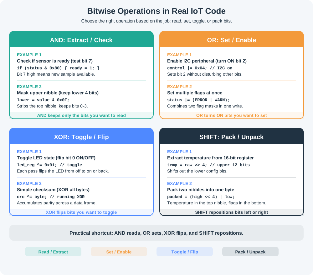
Start from the exact register layout. A 12-bit temperature value may arrive left-justified in two bytes, so the firmware might need raw12 = ((msb << 8) | lsb) >> 4 before signed decoding. If msb=0x19 and lsb=0x00, raw12=0x190=400, giving 25.0 °C. If msb=0xE7 and lsb=0x00, raw12=0xE70=3696; bit 11 is set, so the signed value is 3696 - 4096 = -400, giving -25.0 °C. A robust driver keeps those intermediate values visible in logs or tests so byte-order and shift mistakes are easy to catch.
Use a boundary test before trusting the driver. Feed it 0x000, 0x001, 0x7FF, 0x800, and 0xFFF. The expected signed outputs are 0, 1, 2047, -2048, and -1. Those five cases expose off-by-one thresholds, missing sign extension, and accidental unsigned casts faster than testing only room-temperature readings.
| 12-bit code (hex) | Signed value | Temperature (× 0.0625 °C) |
|---|---|---|
| 0x190 | +400 | +25.0 °C |
| 0x001 | +1 | +0.0625 °C |
| 0xFFF | −1 | −0.0625 °C |
| 0xE70 | −400 | −25.0 °C |
Check the negative case: 0xE70 = 3696. Since 3696 ≥ 2048, the sign bit is set, so the signed value is 3696 − 4096 = −400, and −400 × 0.0625 = −25.0 °C. Reading the same 0xE70 as a plain unsigned number would instead give 3696 × 0.0625 = +231 °C — a nonsense value that is a classic field bug.
Practitioner Knowledge Check
Under the Hood: Sign Extension and Why Two's Complement Won
To load an N-bit two's-complement field into a wider integer correctly, you replicate the sign bit (bit N−1) across all the new high bits. An equivalent arithmetic recipe for a raw code that a register read gives you as an unsigned number: if the raw value is ≥ 2^(N−1), subtract 2^N; otherwise leave it. For 12 bits that is: value = (raw ≥ 2048) ? raw − 4096 : raw. That single line turns 0xFFF (4095) into −1 and 0xE70 (3696) into −400, exactly matching a proper sign extension.
Worked example in binary: the 12-bit code 1110 0111 0000 has bit 11 set, so a 16-bit signed value must become 1111 1110 0111 0000, not 0000 1110 0111 0000. The first pattern is 0xFE70, which a 16-bit signed integer reads as -400. The second pattern is 0x0E70, which reads as 3696. After scaling by 0.0625 °C, the correct value is -25.0 °C; the zero-extended bug prints 231.0 °C. Both results came from the same twelve bits. Only sign extension separated a plausible cold reading from a field failure.
The same idea applies when firmware packs status fields beside data bits. If a 14-bit signed current value sits in bits 15..2 of a register, shift first, mask to 14 bits, then sign-extend from bit 13. Sign-extending before the shift can accidentally treat a status flag as the sign bit, which turns a warning flag into a huge negative measurement.
Two's complement became universal for a concrete hardware reason: the same binary adder handles both signed and unsigned addition, and subtraction is just adding the negative, with any overflow wrapping cleanly modulo 2^N. There is a single representation of zero (unlike sign-magnitude), so no wasted −0 code. That is why nearly every microcontroller register, ADC output, and C int uses it — and why forgetting to sign-extend is such a common IoT numeric bug.