29 ADC Resolution and Vref Contracts
29.1 Start Simple
Imagine a pressure sensor whose datasheet says it changes only a tiny amount for each physical unit. ADC resolution matters only if one code step is smaller than the change the product needs to detect, and accuracy still depends on the sensor, reference, noise, and calibration. Start with LSB size, units per step, and the real-world decision threshold.
29.2 Learning Objectives
After this page, you should be able to:
- Convert ADC bit depth and reference voltage into volts per step.
- Convert volts per step into sensor units using a sensor sensitivity.
- Compare reference-voltage choices by resolution and measurable span.
- Estimate quantization error from the selected ADC step size.
- Decide when extra ADC resolution is below the sensor’s accuracy and therefore not useful.
29.3 Why This Follows ADC/DAC Worked Examples
ADC/DAC Worked Examples teaches the formula-by-formula workflow for converter calculations, sampling, DAC output, PWM approximation, and verification. This page turns those examples into a measurement contract: each count must map to a physical unit, and the chosen reference and bit depth must match the sensor’s real range and accuracy.
Use it when a project is choosing an ADC reference, claiming a temperature resolution, comparing 12-bit and 16-bit converters, or deciding whether calibration and a better sensor matter more than more converter bits.

Phoebe’s Why
This page states the quantization error as \(\pm 0.5\) LSB, which is the honest worst case – the largest a single reading can be wrong by. It is not, however, the typical size of that error across many readings, and that distinction is exactly what the “resolution versus accuracy” argument later on this page needs. Because the true input voltage is equally likely to land anywhere inside one code’s span, the rounding error is a uniform random variable, and a uniform random variable has a specific, calculable RMS size – smaller than the worst case, and it is that RMS size, not the peak, that should be compared against thermal noise, reference noise, or averaging gains when deciding whether quantization is really the dominant error term this page asks you to identify.
The Derivation
A code step \(q\) rounds every input to its nearest center, leaving an error uniform on \([-q/2, q/2]\):
\[\sigma_q^2 = \frac{1}{q}\int_{-q/2}^{q/2} e^2\, de = \frac{q^2}{12} \quad\Longrightarrow\quad \sigma_q = \frac{q}{\sqrt{12}}, \qquad q = \frac{V_{ref}}{2^N}\]
Comparing full-scale signal amplitude to that noise floor gives the standard ideal-converter ceiling:
\[\mathrm{SNR} \approx 6.02N + 1.76\ \text{dB}\]
This is strictly an amplitude-domain result. It says nothing about how often the ADC must sample – that is the separate, time-domain Nyquist question, \(f_s \geq 2f_{max}\), which this page’s own practitioner check correctly treats as unrelated to bit depth.
Worked Numbers: This Page’s Own 12-Bit and 16-Bit LM35 Cases
- This page’s own 12-bit, 3.3 V step: \(q = 3.3/4096 = 0.8057\) mV, so the RMS quantization noise is \(\sigma_q = 0.8057/\sqrt{12} = 0.2327\) mV – versus the page’s own peak figure of \(\pm 0.5\) LSB \(= \pm 0.403\) mV. In the LM35’s own \(10\) mV/°C units, that RMS floor is \(0.2327/10 = 0.0233\ ^{\circ}\text{C}\), smaller than the page’s own quoted \(\pm0.04\ ^{\circ}\text{C}\) peak figure, as the uniform-distribution math predicts.
- Ideal 12-bit ceiling: \(6.02(12) + 1.76 = 74.0\) dB.
- This page’s own 16-bit comparison: \(q = 3.3/65536 \approx 50\ \mu\text{V}\) (the page’s own figure), giving \(\sigma_q = 50/\sqrt{12} \approx 14.4\ \mu\text{V}\) and an ideal ceiling of \(6.02(16)+1.76 = 98.1\) dB – a real 24.1 dB of extra headroom that this page correctly argues is wasted once it falls below the LM35’s own \(\pm0.5\ ^{\circ}\text{C}\) accuracy band, since no amount of quantization refinement changes a sensor’s own error.
Overview: Turn "Bits" Into the Sensor's Own Units
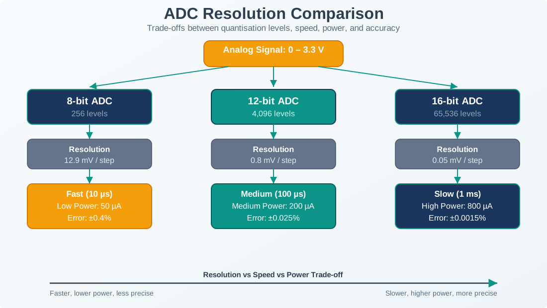
"12-bit" tells you nothing useful on its own. What a design actually cares about is resolution in the physical quantity being measured — degrees, pascals, g’s. The bridge is a two-step chain any datasheet lets you compute:
- Volts per step:
LSB = Vref / 2^N. - Units per step: divide the LSB by the sensor's sensitivity (its volts-per-unit).
The release contract should record each link in that chain rather than only the final headline resolution. Capture the sensor output range, sensitivity, chosen reference, ADC bit depth, volts per code, units per code, quantization error, and the accuracy band claimed by the sensor or calibration procedure. That record makes it obvious whether the extra digit is earned or just printed.
And the measurement span is range = Vref / sensitivity. With those two lines you can state exactly what a sensor-plus-ADC pair resolves before touching hardware.
That is the evidence reviewers need when a dashboard shows one more decimal place than the measurement chain can defend.
The reference-voltage decision is also a range decision. A smaller reference gives finer codes, but it also lowers the largest voltage the ADC can report without clipping. For a field device, leave room for tolerance stack-up: sensor maximum, calibration offset, resistor-divider tolerance, supply variation, and credible fault values. The useful contract is not "12-bit at 1.1 V"; it is "this sensor's accepted range maps to these codes, with this much headroom, and each code is worth this many physical units."
Step 1 — LSB
Vref / 2^N. For 12-bit at Vref = 3.3 V: 3.3 / 4096 = 0.806 mV.
Step 2 — units/step
Divide by sensitivity. An LM35 gives 10 mV/°C, so 0.806 / 10 = 0.0806 °C per step.
Span
Vref / sensitivity. Here 3.3 V / (10 mV/°C) = 330 °C of ADC coverage.
Resolution ≠ accuracy
A fine step does not beat the sensor's own tolerance. The LM35 is only about ±0.5 °C accurate.
A good review therefore asks two questions in order: first, is the code step small enough to see the smallest meaningful change; second, is the claimed change larger than the sensor, reference, and calibration uncertainty. If the first answer is no, adjust reference, gain, or bit depth. If the second answer is no, more bits will only create more-looking numbers.
Overview Knowledge Check
Practitioner: A Reference-Voltage Ledger
Because resolution scales with Vref, the single most effective lever on a small-signal reading is choosing the smallest reference that still spans the range you need. Here is the same LM35 at 12-bit under two references:
| Reference | LSB = Vref / 4096 | Resolution (/10 mV/°C) | ADC span (Vref / 10 mV/°C) |
|---|---|---|---|
| 3.3 V (supply) | 0.806 mV | ~0.081 °C per step | 0 – 330 °C |
| 1.1 V (internal ref) | 0.269 mV | ~0.027 °C per step | 0 – 110 °C |
Dropping from a 3.3 V to a 1.1 V reference makes each step three times finer (0.081 → 0.027 °C) at the cost of a smaller span (330 → 110 °C). Since the LM35 tops out near 150 °C anyway, and few IoT enclosures approach that, the 1.1 V reference is usually the better trade. The quantization error is ±0.5 LSB, so at 3.3 V that is ±0.04 °C.
The ledger should also reserve headroom. If the real input can exceed the nominal range during startup, fault, calibration, or hot ambient conditions, the narrow reference may clip exactly when the diagnostic needs the reading most. The practical acceptance test is to sweep the expected minimum, nominal, maximum, and fault-adjacent values and confirm that all accepted values stay inside the ADC range with margin.
Reference choice is therefore a measured hardware decision, not only a spreadsheet decision. Record whether the reference comes from a regulator rail, internal bandgap, external precision reference, or ratiometric sensor excitation, and verify that its tolerance and drift are smaller than the improvement you expect from the finer code step.
The rule generalizes: pick the smallest reference (or add gain ahead of the ADC) that still covers your real-world range, and you buy resolution for free — provided the reference is a clean, stable one rather than a noisy supply rail.
Practitioner Knowledge Check
Under the Hood: Don't Buy Resolution the Sensor Can't Use
It is tempting to chase more bits. A 16-bit ADC at 3.3 V has an LSB of 3.3 / 65536 ≈ 50 µV, or about 0.005 °C per step on the LM35 — sixteen times finer than the 12-bit case. But the LM35 itself is only accurate to about ±0.5 °C. Those extra bits report changes far smaller than the sensor's own error, so they add digits that are not real information.
This is the resolution-versus-accuracy ceiling stated numerically: resolution is how finely you can distinguish, accuracy is how close you are to the truth. Past the point where one step is comfortably smaller than the sensor's tolerance (a common rule of thumb is a few steps per accuracy band), extra ADC bits buy nothing but noise and data. The right move when you truly need more accuracy is a better sensor, a stable reference, calibration, and averaging — not simply a wider converter.
Under the hood, every code is compared against a reference that has its own tolerance, drift, and noise. If that reference moves by the equivalent of ten ADC counts over temperature, a one-count LSB calculation is not the limiting error anymore. The same is true for amplifier offset, sensor self-heating, PCB leakage, and supply coupling. The resolution contract should name the dominant error term instead of assuming quantization is always dominant.
The acceptance evidence is a small uncertainty budget: quantization error, reference tolerance, reference drift, front-end noise, calibration residual, and sensor tolerance in the same physical units. Once those terms are listed side by side, the decision becomes concrete: keep the cheaper converter, lower the reference, add gain, improve calibration, or buy a sensor whose accuracy actually justifies the extra bits.